


Understanding the Cam and Follower Mechanism: A Comprehensive Guide
The cam and follower mechanism represents a fundamental component in the field of mechanical engineering, playing a pivotal role in the design and functionality of countless machines. From automotive engines to industrial machinery, this integral system facilitates precise motion control, converting rotary motion into linear motion with remarkable efficiency and accuracy. Whether you’re a student, a professional engineer, or simply an enthusiast eager to deepen your technical understanding, this guide serves as your gateway to mastering the intricacies of the cam and follower mechanism. Throughout this article, we will explore its core principles, various types, practical applications, and the engineering considerations that make it an indispensable element in modern mechanical systems. Prepare to uncover the detailed mechanics and design principles that drive innovation across industries.
What is a Cam and Follower?
Definition and Purpose of a Cam
Usually, a cam is designed as a mechanical component that converts rotary motion into oscillatory or reciprocating motion. This is accomplished by integrating a particular type of a shaped cutout known as the cam profile designed to impart specific motion properties to a follower that is in contact with it. Motion is transmitted by the cam through a mechanical connection, and its geometry determines the motion path, speed, accuracy of positioning, and range of movement of the follower. Cams are used in engines, automated machines, and other precision-controlled systems that require cycle-based repetitive motion.
A cam profile is primarily intended to assist a user with control over the motion and the timing within the mechanical system. Through the implementation of intricate designs along the contour’s edge, a follower movement can be dictated with high accuracy, making precision profile traces possible. For example, in combustion engines, due to cam mechanisms controlling the opening and closing of valves along the engine cycles, they are considered to be critical parts of the system. In industrial robotics and manufacturing, sophisticated precision movement enables not only efficiency but also extreme precision, resulting in the wide usage of cams in these industries.
Cam mechanisms are critical in optimizing system performance, and they serve other functions besides the primary role. Cams permit compact designs and eliminate the complexity posed by other systems, like those depending on electronics designed solely for control. Advances in technology, such as computer-aided design or CAD, modern manufacturing processes characterized by high precision, and others serve the functionality of cams by assuring precision in all parts, even the ones that are critically placed. The design and the fabrication technology has been made so much easier that it can be used in areas that are more advanced than ever before, making CAD et al. highly adaptable in further domains. This affirms the persistent progress of lever and cam followers in enabling mechanical systems.
Role of the Follower in Mechanisms
The cam and follower mechanisms cannot operate without the follower, which converts the cam’s motion into the desired output. There are two broad categories of motion the follower may assume, linear or oscillatory, as determined by the type of follower used. Flat-face followers, knife-edge followers, and roller followers are some of the most common types of followers designed for specific operational tasks. This works with the primary function of rotating motion to linear and oscillatory motion, which is important for automobiles, robotics, textile manufacturing, and many more.
The performance and durability of a follower are greatly influenced by its material and design. As with most components, followers are made from hard materials that can withstand wear, like hardened steel or ceramics, because of the continual contact stress with the cam surface. The design also takes into account contouring and lubrication to reduce friction and wear over extended periods of operation. For instance, roller followers are outfitted with antifriction bearings, which enable more effortless motion and minimize energy losses due to friction. The choice of materials in combination with sophisticated surface treatment processes significantly increases the life of the follower while ensuring the dependability of the system.
The design and optimization of followers have received a major boost due to the progress made in manufacturing and computational modeling. Motion videos, together with dynamic simulations, are standard for the analysis of stress distribution and the motion dynamics of specific parts of machines under different loading conditions. Moreover, modern methods of manufacturing make it possible to produce complex shapes of the follower, which were not possible by the conventional ways of machining. These advances help to increase the functionality and effectiveness of cam and follower devices so that they can cope with the exacting standards of contemporary mechanical engineering technology. Alongside the ever-changing technology of followers, these technologies help make it clear how essential they are in the construction of systems with high precision required for progress in almost all sectors.
How Cam and Follower Systems Work Together
In mechanical engineering, the cam and follower systems serve as remarkable units of a machine that transform rotary movement into linear or oscillatory motion with high precision. The cam, which is generally an irregularly shaped disk or a cylinder, rotates about a fixed axis, and the follower is in contact with the cam profiles so that the motion can be transmitted. The design of the cam profile, which determines the path and action of the follower, also guides the motion’s progression. The desired motion sequence can be uniform, variable, or intermittent and is achieved through the geometric relationship between the cam surface and the point of contact with the follower. The system transforms motion required in repetitive cycle operations, for example, in engines, packaging machines, or in automatic assembly machines.
To improve the performance and lifetime of the modern cam and follower systems, new materials and advanced manufacturing processes are used. Cams and followers are now made of high-strength alloys and composite materials, which increases the resistance to wear and deformation under high loads. In addition, detailed, precise machining of the components, for instance, through CNC manufacturing, allows engineers to customize the cam profiles and adjust the characteristics of motion provided to the system. Thanks to these developments, the systems are operated with less energy and benefit from an extended lifecycle, thus increasing the reliability and efficiency of the cam and follower systems.
One primary concern in improving the interaction between cams and followers is lubrication. Maintaining proper lubrication lowers friction and wear, preserves the integrity of motion transfer reliability, and decreases mechanical losses. Again, overheating due to friction is another important factor for the integrity of components over extended periods, thermal management is important too. System efficiency is usually sustained by the use of sophisticated lubricants, in addition to cooling devices, designed to work at different operational levels. The application of sensors for online monitoring, predictive maintenance modeling, and other integrated system monitoring management augments overall system effectiveness by enabling accurate, timely maintenance that averts failure and system downtime. These advancements have further widened the versatility of cam and follower applications in the automotive, aerospace, robotics engineering, and other industries.
Types of Follower Mechanisms
Overview of Follower Types
The cam’s rotary motion is converted through follower mechanisms into a linear motion and is done so in a cam-follower system. The type of follower selected impacts the precision and efficiency output. Using motion as the basis, along with shape and projection needs, followers can be classified. In total, there are four head follower types which are: knife-edge followers, roller followers, flat-faced followers, and spherical-faced followers. These designs differ from one another, which is beneficial as different types of industrial operations would require different functionalities.
- Knife-Edge Followers: A cam surface is contacted by the edge of followers knife which is also known as knife-edge followers. Manufacturers find it easy to design and make these, but the pointed edge feature requires a lot of work leading to shorter lifespans. When systems have no need for precision or have low-load requirements, this follower type works best. Even with all these issues, extreme engineering techniques can override a few of the problems, such as surface hardening and lubrication.
- Roller Followers: Friction is minimized further in roller followers than in knife-edge followers because they have a cylindrical roller at the point of contact with the cam surface. The reduction in friction further increases efficiency and reduces wear, which makes roller followers very appropriate for high-speed and high-load applications like automotive engines. In addition, roller followers are very good at controlling variable loads, which demonstrates adaptability to changing operational conditions. Advanced roller followers compete in the market with the addition of modern materials of construction such as ceramics or thermal resistant coatings such as DLC (Diamond-Like Carbon).
- Flat-Faced and Spherical-Faced Followers: The surface of flat-faced followers that engages with the cam has a flat profile. With this design, the force applied at the contact area is spread evenly throughout the contact area, reducing stress and wear. These followers are often used in systems that involve precise control of motion like textile machines or fuel injection pumps. On the contrary, followers with a curved surface are called spherical-faced followers and are designed to compensate for small offsets between the cam and follower. This characteristic is useful in systems with a need for high-precision motion and alignment tolerance.
Taking into account recent progress in material science and engineering, follower mechanisms are changing in new ways to satisfy modern application requirements. Choosing the best follower type for a given purpose must take into account the load’s behavior, speed, degree of friction, and ease of maintenance.
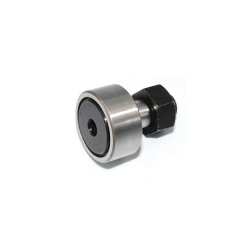
Characteristics of a Roller Follower
A roller follower is a form of cam follower that incorporates a roller, which may either be a needle or a cylindrical roller. This configuration significantly improves the mechanism’s efficiency and lifespan by minimizing the frictional losses that occur during motion. The roller reduces sliding contact to rolling, yielding less thermal and mechanical damage. This meticulous guiding and lesser mechanical damages make roller followers crucial components in advanced engineering systems, from robotics to automotive engines and industrial machines.
A roller follower is defined by its capability of smoothly handling large radial and axial loads. This is due to the construction of the roller and its housing, which are made of hardened steel or other similarly strong materials. The mechanism allows for excellent load-bearing even under continuous, high-speed operation by distributing forces evenly across the surface of the roller. Additionally, the use of advanced surface treatments such as nitriding or carburizing increases wear resistance, enabling operation in harsh or abrasive environments.
Another important distinction is the capability of precise alignment of roller followers. The rolling element is usually fitted on a linear motion system on the shaft or an accurate bearing, which provides either linear or rotary motion. This alignment is very important to the stability of the system because it minimizes vibration, which is crucial for many sensitive applications such as CNC machines that require rigorous compliance to set limits where even the smallest positional errors could cause malfunction. Roller followers also provide significant rotational precision, which can be enhanced further by attention to defined lubrication or maintenance schedules.
An additional important benefit provided by roller followers is thermal management. Due to the rolling mechanism having less friction than sliding mechanisms, there is less loss of energy as heat. Furthermore, modern designs now feature sophisticated lubricating aids such as sealed pre-lubricated units or systems with synthetic grease which provide reliable performance over long periods without maintenance.
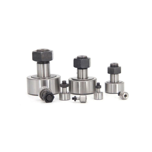
Lastly, roller followers are adaptable regarding how they are mounted. They can be standard or flange mounted, which gives them a broad range of applications and flexibility for system designers. Innovations in manufacturing methods like precision machining and additive manufacturing have increased the customization options for roller followers. This helps tailor the followers to specific needs, such as severe environmental conditions or complex motion profiles. This makes sure that roller followers are still used across many industries that need precision, durability, and dependability.
Differences Between Knife-edge and Flat-faced Followers
The knife-edge and flat-faced followers exhibit unique design characteristics that impact their operational suitability, applications, and lifespan. Unlike flat-faced ones, knife-edge followers have pointed, thin contact surfaces that touch only a small area of the cam. These followers experience the least friction, but higher pressure from the cam surface. Due to the stress concentration on the contact area, knife-edge followers are better suited for applications requiring soft drive transmission and lubrication. However, such followers with high wear rate do not work well for the wear-focused application.
In contrast, flat-faced followers are not suited for knife-edge applications due to their broad and flat contact surfaces. The contact area of flat-faced followers is greater than that of knife-edge followers; hence, they uniformly distribute load over a larger area. Since surface pressure and wear are low, flat-faced followers can sustain higher loads without failing for significantly extended periods compared to knife-edge followers. Moreover, these followers are cam versatile due to the ability to withstand more complex cam profiles like sinusoidal or offset geometry without the risk of mechanical failure. Although the geometry of flat-faced followers has certain advantages, the increased area also means greater frictional resistance, which may require advanced lubrication systems to maintain performance.
Furthermore, both the operating conditions and the environment of a specific movement often dictate the selection between flat-faced and knife-edge followers. In scientific instruments or where components are responsive and light, knife-edge followers tend to be used in precision systems. On the other hand, flat-faced followers are quite helpful in more heavy-duty engineering works like in automobile valves, trains, or industrial machines, which are more concerned with durability and the ability to carry loads. The difference made in performance versus longevity enables engineers to decide on the follower most appropriate for the system design.
Exploring Different Cam Mechanisms
Understanding the Cam Profile
The cam profile is particularly important when designing a cam mechanism because it controls the motion given to the follower as well as the next components in line. The profile is given specifically by the motion diassociated with the contour of the surface of the cam, either linear or rotary, and the follower. The motion desired is achieved by balancing accuracy, efficiency, and durability, and in most cases, cam profiles are meticulously crafted. These profiles can range from simple circular arcs to complex, asymmetrical shapes tailored to meet specific engineering requirements.
Cam profiles can be differentiated into different categories, such as radial or axial profiles. In the case of radial cams motion, the follower is to move begrimed to the axis of the cam will be perpendicular to it. Axial (and cylindrical) cams are used in machinery and allow motion perpendicular to the axis.
Moreover, the performance of a cam profile is influenced by the selection of materials and manufacturing processes. CNC machining, particularly high-precision processes, guarantees the specific accuracy required in the crafting of the profile. Additional processes like surface hardening or nitriding treatment improve durability and wear resistance, especially for demanding operational environment cams. Such design and construction harmonies guarantee that the cam profile functions optimally in automotive valve trains and other more complex systems such as industrial automation.
Examples of Cylindrical and Globoidal Cams
Cylindrical cams are prevalent in automated machines and consist of a rod with a groove carved out of its surface. The follower in a cylindrical cam system executes the oscillatory or linear motion of a translational shaft and rotates a rod corresponding to a pin mounted on the cam. Rotational motion is converted to oscillatory or linear movement as the groove is traced. For instance, in a weaving machine, the cylindrical cam acts to ensure that mechanized looms are in phase with each other so that the fueling and weaving processes are executed in parallel for maximum efficiency.
Globoidal or hourglass cams are frequently used in high-speed index devices, like a rotary indexer mounted on automated assembly machines. Unlike cylindrical cams, they have hourglass-shaped bodies equipped with tracks or grooves intended for multi-follower’s linkage. A good instance could certainly be found in bottling machines where they are needed to precisely and reasonably fast facilitate exact positioning and retaining of the bottles open during the process of filling and capping them. With the aid of these cams, several thousand pieces of goods are transported per hour.
The aforementioned cam types represent attempts at resolving specific mechanical problems using engineering-oriented approaches, highlighting the ever evolving designs in modern industry which focus on accuracy, bearing load, and lifespan.
Working Principle of the Cam and Follower Mechanism
How the Cam Rotates and Drives Motion
As a cam rotates, its unique contoured surface motions a follower in either a linear or oscillating direction. The follower’s movement profile is determined by the path the cam moves along. To give another example, in a radial cam mechanism, the follower is almost perfectly guided along a guide, which allows it to be properly positioned concerning the surface of the cam.
The cam is usually driven by some external device like an electric motor or a combustion engine which have constant rotational speeds. The follower and cam work together with only a specified amount of forces in contact with each other, called contact force. To achieve this, sands and other soft materials are incorporated so that there is no friction and wear. This results in massive imrovement to the lifr of the system.
Practical cases highlight the accuracy of such mechanisms. For instance, in automotive engines, camshafts control the timing of valve intakes and exhausts in sync with piston movement for optimal performance. The car’s speed, which is typically measured in RPM, is directly proportional to cam performance outcomes at higher engine outputs. This precision in cam follower systems with micrometer tolerances is of grave importance.
Interaction Between Cam and the Follower
The relationship between the cam and the follower is of paramount importance in the functioning of mechanical devices, particularly in sophisticated machinery. The essential role of a cam is to change the direction of the wheel’s turn into a linear or oscillatory movement of a certain degree within set limits. This is done through contact between the follower and the cam profile. The cam governs the motion of the follower, and the motion is preconditioned by the geometry of the cam.
Hardened steel or ceramically coated components are widely accepted as reducing friction as well as enduring extreme loading. The same applies to lubricants in terms of reduced wear, thermal stabilization, and shiftable loads, especially under high-speed conditions where the cam and follower experience intense friction forces.
The analysis of cam-follower systems kinematics commonly includes monitoring pressure angle, follower displacement, velocity and acceleration. Through modern engineering computational models and testing techniques, the cam-follower mechanisms used in automotive engine and industrial robotics are enhanced to meet cutting engineering standards of precision and reliability.
Conversion of Rotary Motion into Linear Motion
The rotary to linear motion conversion using CAMS, lead screws, and the more ubiquitous rack-and-pinion is a fundamental principle across all disciplines of engineering. One of the best examples of this is the cam follower system where the rotational input of the cam is converted into linear output motion of the follower.
In contruction, more demanding applications are best served with the precision provided by ball screws and ball screw actuators. Due to their design, Ball Screws can minimize friction and transform smooth rotary input into highly accurate motion. For this reason, CNC machines and robotic arms commonly employ these tools. The reliability of these systems has increased as materials science has continued to improve, incorporating low friction coatings and high stress/ wear resistant alloys.
These mechanisms are increasingly employed in automobiles as they tend to integrate more easily with powered steering systems. More industrial rack and pinion use includes industrial machinery, where they provide increased efficiency.
In aerospace applications, emphasis is placed on low-density materials and exacting tolerances to maximize performance and efficiency. Innovations in the design of motion conversion systems still seek to attain ever-increasing industrial requirements on precision, velocity, and dependability.
Applications of Cam and Follower Mechanisms
Industrial Uses of Cam Followers
The cam and follower mechanism is one of the most widely used mechanisms in different sectors because of its accuracy in changing rotary movement to linear motion. These parts form the basis of a manufacturing system where they are used in automated machines for rudimentary processes like cutting, stamping, and shaping. As an example, cam followers in high-speed packaging lines help maintain the productivity and efficiency of the packaged materials by ensuring proper synchronization of the other lower level components.
In automotive manufacturing, cam followers are equally important as they perform in internal combustion engines for the efficient operation of the intake and exhaust valves. Modern designs of cam followers are made out of high-carbon steel and engineered polymers, which are designed to endure extreme friction and wear, therefore guaranteeing reliability even under heavy operational loads.
With the development of new technologies, cam follower devices have also become equipped with lower friction coatings and advanced lubrication systems, which lessen maintenance needs dramatically. This benefits many industries, such as aerospace and precision engineering, where reliability and longevity of components are essential. All these changes demonstrate the use of cam followers in industrial automation and system optimization.
Role in Engine Systems
Engine systems operate smoothly because cam followers convert rotary motion to linear movement with great accuracy. In conjunction with other components like valves, pistons, and internal rotors, cam followers aid in the versatile control of internal combustion engines, and they ensure a high degree of precision in timing and sequencing, minimizing the chance of failure and enabling optimal function.
Modern followers are more effective in withstanding high temperatures and pressure in high-performing engines because of advancements in material science. Enhanced alloys that undergo heat treatment and ceramic coatings significantly improve thermal resistance. Additionally, with better bearing designs, radial, attainable, and circumferential bearing wear is reduced, which extends service life. Incorporation within variable valve timing (VVT) systems also greatly improves engine efficiency, fuel consumption, emission levels, and performance, which are important for compliance with emissions standards in the aviation and automotive industries.
Cam followers impact the life cycle of engine systems because of their performance, so they are essential in precision and endurance demanding tasks. This outlines the engineering complexity of cross-section cam followers in modern and future driven engines, underscoring the value of innovation.
Frequently Asked Questions (FAQs)
Q: What is the cam and follower mechanism?
A: The cam and follower mechanism is a mechanical system used to convert the rotational motion of the cam into linear or oscillating motion of the follower. This system is widely used in various applications, such as internal combustion engines.
Q: What are the different types of cam?
A: There are several types of cams, including disk or plate cams, cylindrical cams, translating cams, and roller cams. Each type of cam has a specific profile and is used based on the required motion of the follower.
Q: How does the working principle of a cam-and-follower mechanism operate?
A: The working principle involves a cam, which is a rotating element, imparting motion to the follower. As the cam rotates, its profile comes into contact with the follower, causing it to move in a predetermined manner, whether it be translating or oscillating.
Q: What terminology is important to understand in a cam and follower mechanism?
A: Important terminology includes the profile of the cam, the point on the follower, the center of the cam, follower motion, and the displacement of the follower. Understanding these terms helps in designing and analyzing the cam and follower assembly.
Q: What is the role of the follower in the cam and follower mechanism?
A: The follower is a mechanical component that moves as it follows the profile of the cam. Depending on its design, the follower can have different types of motion, such as a translating follower or an oscillating follower, and can be spring-loaded or have a flat surface.
Q: What are the common applications of cam and follower mechanisms?
A: Cam and follower mechanisms are used in applications like automotive engines, automated machinery, and valve actuators. They provide precise control over motion, making them essential in systems where specific follower motion is required.
Q: How does the shape of the cam affect the motion of the follower?
A: The shape of the cam determines the path and type of motion imparted to the follower. For example, a cam with a complex profile can create intricate follower movements. The rotation of the cam and its profile directly influence how the follower moves along its path.
Q: What is the difference between a translating cam and a stationary cam?
A: A translating cam moves linearly along its axis, causing the follower to move in a linear path. In contrast, a stationary cam remains fixed in place while the follower moves around or along it, typically resulting in complex motion patterns.
Q: How does contact between the cam and the follower affect performance?
A: Contact between the cam and follower is crucial as it directly impacts the efficiency and wear of the system. Proper contact ensures smooth transfer of motion, while poor contact can lead to increased friction and wear, affecting the system’s longevity and performance.
Q: What happens when the follower has a flat surface?
A: When the follower has a flat surface, it maintains constant contact with the cam profile, resulting in smooth and consistent follower motion. This design is often used when a uniform displacement of the follower is required.

UCTH213-40J-300 with Setscrew(inch)
CNSORDERNO: Normal-duty(2)
TOGN: UCTH213-40J-300
SDI: B-R1/8
SD: 2 1/2
UCTH212-39J-300 with Setscrew(inch)
CNSORDERNO: Normal-duty(2)
TOGN: UCTH212-39J-300
SDI: B-R1/8
SD: 2 7/16
UCTH212-38J-300 with Setscrew(inch)
CNSORDERNO: Normal-duty(2)
TOGN: UCTH212-38J-300
SDI: B-R1/8
SD: 2 3/8
UCTH212-36J-300 with Setscrew(inch)
CNSORDERNO: Normal-duty(2)
TOGN: UCTH212-36J-300
SDI: B-R1/8
SD: 2 1/4
UCTH211-35J-300 with Setscrew(inch)
CNSORDERNO: Normal-duty(2)
TOGN: UCTH211-35J-300
SDI: B-R1/8
SD: 2 3/16
UCTH211-34J-300 with Setscrew(inch)
CNSORDERNO: Normal-duty(2)
TOGN: UCTH211-34J-300
SDI: B-R1/8
SD: 2 1/8