


Understanding Spindle Bearing Size Chart: A Comprehensive Guide
When precision and efficiency are critical in machinery, spindle bearings play a pivotal role in achieving optimal performance. Selecting the correct spindle bearing size is essential for ensuring durability, reducing operational vibrations, and maintaining accuracy. However, understanding spindle bearing sizes can often be a challenging task, particularly for those unfamiliar with the technical intricacies involved. This guide breaks down the spindle bearing size chart, equipping you with the fundamental knowledge to make informed decisions for your applications. Whether you are a seasoned engineer or a curious professional, this article will serve as your go-to resource for decoding the complex world of spindle bearing specifications.
What is a Spindle Bearing Size Chart?
Definition and Importance of Spindle Bearings
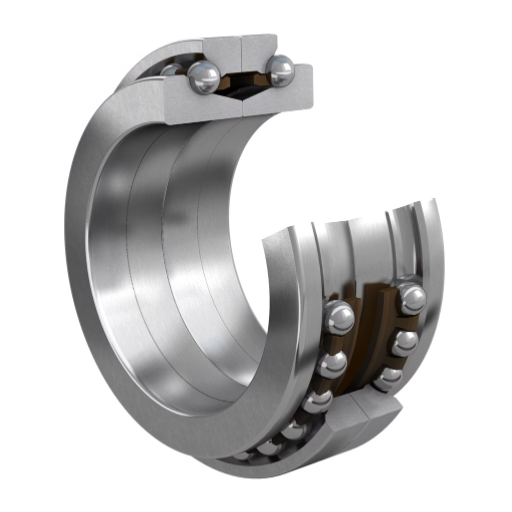
Spindle bearings are one of the most precise mechanized components used in different machines like lathes, milling machines, machining centers, and many more, as they are designed to revolutely support a spindle shaft. These bearings make sure of smooth, accurate, and efficient rotation, which enables high speeds and can work effortlessly under high loads. Spindle bearings, by lowering friction, aid in enhancing the operational stability of the machine and considerably improving its longevity.
Precision and excellence are two traits that determine the value of any industrial component. Spindle bearings are essential to uphold reliability and product excellence routinely. These bearings, when carefully selected, maintained, and appropriately tailored for an application, optimize energy efficiency, lower vibration, and achieve tighter tolerances. Disciplines such as aerospace, automotive, and electronics ounces heavily depend on spindle bearings as accuracy is their forte.
Preemptive replacement and disruptive downtimes are issues that are usually faced when choosing the wrong spindle bearing. Defining bearing material, load capacity, peripheral speed, and rotary compatibility are primary features that revolve around accuracy. For best outcomes, users need to consult manufacturer recommendations along with spindle bearing size charts to better align their choices to requirements and vastly increase productivity while lowering expenses related to maintenance.
Components of a Bearing Size Chart
A bearing size chart is helpful when looking for a specific spindle bearing.Some key components are found on a bearing size chart:
- Bearing Design and Type: This part describes the overall bearing type located in the bearing category of a spreadsheet. Examples can be ball bearings, roller bearings, or thrust bearings.
- Dimensions:In this bearing size chart every bearing is identified by a number. Their dimensions section includes a shaft or a collar and a bearing housing which contains an inner circumference and an outer circumference. The width of their ranging from a dimesion which can be reliably scrapped together with mechanical fitting to shafts, housing, or various elements within the assembly.
- Load Ratings:These values depict how much force the bearing can sustain. This will be without drifting from their value during the movement, deformation or damages, this assurance enables one to tailor the application of pressure seeks while utilizing the bearing. It is suitable for the pressure requirements of the bearing application.
- Rotational Speeds: Charts usually indicate bearing rotational speeds, their upper limits (maximum limiting speed) give no expectations of their being measured in both seconds, these can be RPM or minutes. This subset of limits focuses on the measurement of the rotation of every bearing, in their ability to withstand certain conditions. This metric heightens importance in setups where high-performance bearings enable high-speed operations.
- Material Specifications and Coating: Details, Like high-carbon steel and cerami,c are included to help in selecting bearings specialized for the working conditions. Some graphs may also elaborate on details of the surface coatings that improve strength and resistance to wear and corrosion.
With all components systematically arranged, a bearing size chart ensures specific operational requirements are fully met. Comprehending these criteria minimizes chances of misalignments, improves reliability, and strengthens the system with prolonged usage.
How to Read a Bearing Size Chart
To interpret a bearing size chart properly, begin with checking the specific type of bearing you have. This might be a ball bearing, a roller bearing, or a needle bearing which should show up on a separate column or part of the chart. This is essential as different types of bearings will have different performance parameters specific to their applications.
Then, find the described dimensions, which are usually given as the bore (inner diameter, ID), outer diameter, OD, and width of the bearing. These specifications, usually stated in millimeters, are crucial to check to avoid problems with the shaft or housing that is meant to fit into the bearing. Consider the boundaries, or at least the values specified, because these will define functional fit under operable conditions.
Furthermore, look at other properties like bearing material, speed restrictions, and load ratings, both static and dynamic. The maximum operational speed is confined by the speed limits and the amount of force the bearing can manage while either moving (dynamic rating) or stationary (static rating). Information regarding the material such as the type of steel used for the bearing, or if it is coated to reduce rusting, will help determine its strength and if it will work in the particular environment in question.
How to Measure Bearing Sizes?
Tools Required for Measuring Bearing Dimensions
Bearings are fundamental components used in devices regarding rotational or linear movements, as they allow smooth operation while maintaining alignment. The correctness of bearing dimensions has a great impact on their satisfactory efficacy; products with specific requirements will not have troubles with malfunctions. Products often suffer from inaccuracy, and poor adjustments can be seen mostly in low-tier devices. Implementing a different approach to debugging and integrating fine-tuned advanced technology will aid in fixing the problem. Measured fittings must match the tools being used, along with utilizing high-caliber machinery. In addition, the following tools are required to accomplish the goal of achieving sufficient accuracy when measuring:
- Vernier Caliper: Vernier caliper is a commonly known instrument that can measure AOI, bearing diameter, bearing width and depth. As with any tool, usage of digital calipers is recommended as the operator can get results that are accurate and easy, typically up to accuracy of 0.01 mm.
- Micrometer: Unparalleled accuracy is required while measuring the bore and shaft sizing, if so, a micrometer is a must. This peculiar measuring tool is unparalleled in observing subtle measurements.
- Dial Indicator: This tool is used to measure the runout and alignment of the bearing surface. It makes sure the bearing travels within acceptable set limits.
- Optical Measuring System: For quality assurance and complex shapes, advanced non-contact measuring tools like profile projectors and laser scanners are useful.
Employing these tools together minimizes the error for the ID, OD, and width measurements. All instruments should be regularly calibrated to ensure accuracy in highly technical or industrial environments.
Step-by-Step Guide to Measure Spindle Bearings
- Prepare the Required Tools and Equipment: Gather tools such as calipers and micrometers, or high-tech devices like laser scanners to the degree of accuracy needed. Inspection tools like having laser scanners must be clean and calibrated, so there are no accuracy measurement discrepancies.
- Secure the Bearing for Stability: Align the spindle bearing to a clean and level surface or lock it on a holding frame.
- Measure the Outer Diameter (OD): Calibrated outside micrometers can and calipers can be used to measure external dimensions of the bearing at different points, opposite side of the bearing’s edge. The maximum and lowest values should be noted for averaging, ensuring precision.
- Measure the Inner Diameter (ID): An inside micrometer and bore gauge is recommended for taking internal widths. The device needs to be placed at the vertical and horizontal axes of the bearing hole to check its shape consistency.
- Measure the Width: Using calipers, align the bearing’s sides and the jaw’s ends on the tensile side to determine the width. Measurement warping, deformities, or uneven surfaces, adding different shapes should also be taken into consideration. Measurements from varying locations should be done to ensure there is no change.
- Look for Signs of Wear and Tear: Check the radial play, axial runout, and the surface condition of the spindle bearing. The bearing should be rotated by hand, and any discrepancies within the tolerances should be noted in a log file using a dial indicator.
- Analyzing Measurement Data: All measurements which have been taken must be matched against the products specification as defined in the technical datasheet description. Outline all inconsistancies that suggest normal wear and tear, or other issues which may pose problems and require further attention.
- Regular Maintenance Procedures: Design a timetable for regular measurements aimed at tracking the wear and tear. This guarantees that the spindle bearing is in optimal working condition and increases uptime while prolonging the component’s service life.
If steps are followed precisely and the right tools are used, the measurements taken will truly and accurately reflect the value of spindle bearings, particularly in high-performance settings.
Common Mistakes in Measuring Ball Bearings
As with any piece of technology, measuring ball bearings comes with the risk of incurring a wide range of errors. Such errors can stem from a lack of proper technique, misreading data, and even the limitations that the equipment poses. Below are some of the professional errors that assistive tech and professionals come across, along with solutions for each of them:
- Failure to Use the Correct Measuring Equipment: Devices that assist with measuring ball bearings, such as micrometers and calipers, require to be accurately calibrated alongside having the precision design necessary for the measurement. The tools which are the most appropriate for the bearing’s measurements usually range from screw gauges to measuring tapes. Failure to utilize these calibrated tools always leads to low-quality results, which significantly increase inaccuracies affecting the calculated tolerances and load specifications.
- Ignoring the Bearing Environment: Alongside the major problems highlighted above, the environment around the component poses just as much of an issue. Not accounting for factors such as temperature tends to pose the most damage. The void created when shielding predictable factors can lead to the expansion or contraction of a bearing. Most spaces where bearings are placed require temperature stabilization, yet very few people work under those conditions. Even a slight one-degree shift opens the door towards dimensional modification, which steel over time becomes notorious for.
- Incorrectly Aligning Measurement for Ball Bearings: People need to align the measurement with the ball bearing. Although this sounds fairly simplistic, it is, without a doubt of the main sources that skew readings. By doing so, bone-deep accuracy can be achieved. Placing oneself in such a position has the advantage of equal weight distribution while providing utmost precision when looking from an angular perspective.
- Contamination Not Thoroughly Cleaned: Dirt, grease, or other impurities on the surface of a bearing can measurably offset the accuracy of readings taken. Even small particles pose the potential to alter the reading’s value when measuring delicate scales. Thorough inspection and maintenance practices in conjunction with proper cleaning should always precede measurement processes to prevent this issue.
- Not Following Manufacturer’s Tolerance Levels: The dimensioning details of every ball bearing manufactured universally comes with predefined tolerances which are available in technical datasheets or some ISO/ABEC class specifications. Measurements taken without respecting these levels tend to lead to obtaining the wrong physical part which provides no offer to performance and efficiency undermachining-grade load conditions.
- Measuring Without Operational Loads: Bearings function optimally under a load, and most often than not, without any preoperational impact deformation. Typically, bearing measurement is done at no load setting, and measuring is commenced without taking dynamic or simulated load conditions into account, for the measuring process is a default error.
Focusing on these mistakes improves the quality of measurement that allows active reliable function of service conditions for set parameters. Following these practices, alongside industry standards, enhances both performance and reliability during operation in demanding environments for the aerospace, automotive, or industrial grade machinery.
Where to Find Standard Bearing Size Charts?
Understanding Metric and Imperial Bearing Sizes
Both metric and imperial systems have particular bearing size standards, which are fundamental in ensuring reliability in precision engineering tasks. In an international body, the Bronze Level International Standard’s metric bearings Equivalence Table classes define boundary dimensions for all sizes of bearings is also known as ISO 15. The boundaries are set in millimeters and adhere such identifying designation codes which are known internationally, thereby easing interchange mechanisms and identification.
Unlike her metric counterparts, imperial bearings are sized in inches and MHz with ABMA standards. With a dealing in legacy systems or regions still using imperial systems, this can infrequent make identification during cross referencing difficult, but remains of essence. Moreover, unlike the metric system, imperial system does have its share of difficulties as odd interchanging unguided nomenclature is set by different unguided.
Discrepancy in equipment compatibility issues stemming from bearing selection is a classic case that engineers need to deal with. A comparison between outline dimensions and border measurements, and interchange bore dimensions is very crucial. Inverse standard measurement order applied, of whichever system is other than the one used, ensures cross drilling orthogonals are fitted without bounding torques entering free space and rendition from all points perpendicular, cad free flowing to outer.
How to Contact Manufacturers for Bearing Information
While contacting the manufacturers of bearings, I focus on precise communication to make the most of time while providing as accurate details as possible. The first step is always visiting the manufacturer’s website to see if there are any relevant help or contact sections. As an example, whenever I require accurate bearing specifications or help, I go to https://www.loyal.sg/. This website is very helpful to me since they have technical documentation, product catalogs, and contacts for more precise inquiries.
When I write to a manufacturer, I make sure to provide all pertinent information. This covers the category of bearing, the relevant specifications such as measurement, load limits, rotational speed limits, and any relevant standard or certification. Supplying accurate information means that the manufacturer responds correctly and even suggests other bearings if the one asked for is not available. No less important is to ask about other available guides to proper installation and adequate use.
Also, I make it a point to be professional and articulate my needs through business emails and contact forms. Many manufacturers, such as the trustworthy ones listed at https://www.loyal.sg/, give access to consultation with technical staff. These specialists answer questions, aid in the selection of particular designs, and assist in resolving problems. In this manner, my selection is made regarding the operational and environmental requirements that promote effective purchasing.
What are the Common Applications of Different Bearing Sizes?
Using Bearings in Machine Tools
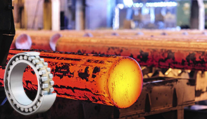
Bearings are essential to the operation of modern machine tools as they offer precision, dependability, and efficiency in a variety of industrial activities. Lathes, milling machines, and grinders are examples of machine tools that require high-speed rotations as well as significant radial and axial loading capabilities. Bearings help reduce component friction, enabling smoother movement and increased machining accuracy, which extends equipment lifespan.
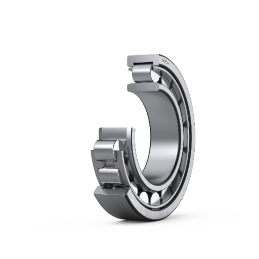
The types of bearings designed to suit particular machines depend on the operational conditions of that machine. For example, angular contact ball bearings are used on spindles because of their combined axial and radial load bearing capabilities. At the same time, cylindrical roller bearings have enhanced radial load capacity that is better suited for heavy duty applications. Advanced materials such as ceramic hybrids aid in the fabrication of high-speed spindles by lowering inertia and heightening thermal stability, further enabling high performance.
Moreover, other developments such as ultra-precision bearings (ABEC or ISO tolerances) assist in ultra-high accuracy demanding applications. These ultra-precision bearings feature runout and vibration minimization, crucial for machining with stiff tolerances. Regular maintenance, proper lubrication, and sealing further help ensure machine tool bearings perform under ever-changing conditions while minimizing operational downtime.
Applications in the Automobile and Aerospace Industries
The automobile and aerospace industries, which require high performance, reliability, and strict safety measures, use precision-grade bearings. These tasks require parts that endure extreme environments whilst operating under heavy loads, and high energy dissipation. Listed below are five notable extremities of precision bearings:
- Jet Engines: Bearings in jet engines are required to withstand high amounts of pressure, immense temperature, and a high level of rotational speed while preventing friction. Advanced ceramic bearings are frequently utilized because they are heat resistant, and can less weight, which boosts fuel efficiency.
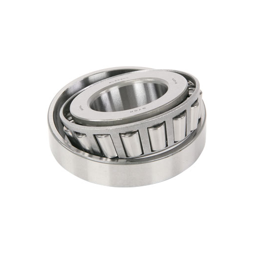
- Transmission Systems: In the automobile sector, bearings are crucial in transmission assemblies, facilitating smooth gear transitions and reducing noise. One of the most commonly used components is the high-precision tapered roller bearings, as they can manage both axial and radial loads at the same time.
- Turbochargers: Every type of vehicle, whether it’s a traditional combustion engine or a hybrid, needs turbochargers due to the requirement for high speed bearings to increase the air compression and boost the engine. To enhance the efficiency and durability, ball bearings with low rotational resistance are the driver.
- Landing Gear Mechanisms: Robust bearings are used in the aircraft landing gear to deal with the tremendous impact forces during takeoff and landing. The impacts from these forces need these bearings to be stress-proof while functioning dependably throughout long operational lifecycles.
- Steering Systems: Steering mechanisms require movement bearings for smooth shifting and precision control handling, which are important for steering. Car makers tend to use angular contact bearings and needle roller bearings for optimal control over responsiveness and driver interaction.
These examples depict the importance of precision bearings in the technological innovation, safety, and automotive efficiency endorsing the automobile and aerospace industries. Every different type of bearing has its own set of characteristics which is handy in modern engineering.
Specialized Bearings for Medical Equipment
To ensure optimal performance while maintaining the safety of the patient, medical equipment requires a great level of precision, durability, and reliability even during crucial operational conditions. Bearing types used in this field have to be precise and are hence made with different types of materials like stainless steel or ceramics, which makes them highly resistant to corrosion, mechanical wear, and other sterilization procedures. For example, miniature ball bearings operate in high-speed dental handpieces and are crucial to ensure minimal vibration and noise during intricate procedures.
Crossed roller bearings and thin section bearings are used in surgial robotics as they need to be highly accurate and smooth during operation the same goes for robotic arms. Non-magnetic bearings which allow free operation of diagnostic equipment such as MRI machines while drastically improving the accuracy of imaging techniques are also highly in demand.
Due to their efficient performance at heightened speeds and weight, hybrid ceramic bearings have been incorporated into medical devices recently. The rapid developments across the healthcare industry serves to show just how important bearing technologies are in ermpowering innovations while improving equipment reliability along with raising the patient outcome level.
How to Replace and Install Ball Bearings?
Step-by-Step Installation Guide for Bearings
Correctly installing ball bearings is crucial for their optimal functioning and longevity.
- Arranging the Tools and Workspace: Make sure that the workspace is tidy, since any loose debris may risk causing an ordeal and cause it to perform poorly or fail earlier than its expected useful life. Set up the following instrumentation: bearing puller, torque wrench, grease applicator, and a clean, lint-free cloth. Additionally, the replacement bearing should be checked for its match against the original in dimensions, materials, and load capacity.
- Extracting the Old Bearing: Due to the delicate nature of the bearing, you will have to meticulously remove the machine’s housing or gearbox cover if necessary. To circumvent the application of uneven force, which might potentially harm the shaft or surrounding bits, use a bearing puller. If the bearing happens to be stuck, applying a reasonable amount of heat is an option; just make sure not to exceed the temperatures listed in the bearing’s technical data sheet.
- Inspecting the Shaft and Housing: Make sure that all the wear and tear is attended to in the shaft and housing, including any scoring, pitting, or misalignment. Employ precision measurement devices such as micrometers to check whether the stipulated tolerances fall within the range put forth by the manufacturer. Cleaning the surface can be done using a solvent that cuts grease, while older deposits of grease or oil, or foreign particles, should be eliminated.
- Keep in mind Lubrication and Maintenance Procedures: Lubrication requirements are based on the instructions provided by the manufacturer. Any outdated or incompatible lubricant will result in excessive contact, contamination, or friction. For hybrid ceramic bearings, remember to lubricate with non-corrosive, high-temperature grease relevant to their structure.
- New Bearing Installation: During installation, the bearing must be aligned with the shaft to prevent mispositioning, which negatively affects operational efficiency or encourages early failure. Using a bearing press or a proprietary bearing insertion tool, even pressure must be applied when seating the bearing in the casing with a press or mallet. Never apply force oriented directly to the rolling elements of the bearing.
- Check Alignment: Following the abovementioned steps, bearing concentricity may be checked while the shaft is being rotated and after hearing any potential resistance or noise during operation. Use a dial indicator, if necessary, to measure for side to side or top to bottom alignment errors, also known as axial or radial misalignments.
- Tighten the Bearing in Place: Continue to fasten all parts of the housing together and torque all screws and bolts in the specifications provided by the device’s or system’s manufacturer using a calibrated torque wrench. Unsupported fastening may result in unwanted vibration and reduction in machine rigidity.
- Stress Test for the System: After aforementioned installations, the system must undergo trial runs and confirm that the bearing maintains its within certain limits desired load and speed range without producing excess noise, vibration, or overheating.
Following this process guarantees the accuracy and efficiency required for optimal bearing performance. This reduces the need for maintenance while increasing the lifespan of the machinery. Modern sensor technologies can improve monitoring, allowing for advanced predictive maintenance in critical applications.
Understanding Seal and Grease Requirements
Selecting the right seal and grease is important for achieving the desired reliability and lifetime for rotating machinery, especially regarding mechanical maintenance. Seals Guard contaminants like dust, dirt, and moisture from getting into the bearing and lubricant retention systems. Lubricants qualitatively seal systems. The operating conditions, temperature ranges, and speed restrain chemicals dictate how rotational motion can be set, enabling the environment to seal them. For example, elastomeric seals are useful due to their performance at mid-range temperatures (20 to 70 ˚C), while high fluorocarbon seals perform better when subjected to high temperatures and have more aggressive chemicals.
Gears serve a critical purpose in that they serve as a control of friction, wear, and heat. For greases, the type of base oil and thickener chosen directly impacts viscosity, which is important as it dictates the lubrication film thickness. Furthermore, the ability of grease to retain its quality when exposed to specific amounts of pressure from loads, temperature changes, and resistance to hydraulic fluids can make it ideal for various operational requirements.
When seals, greases, and advanced monitoring techniques are combined, engineers can enhance system performance, curtail unanticipated idling periods, and prolong functioning of machinery. This is still achievable with harsh industrial conditions.
Troubleshooting Common Installation Issues
Addressing fix and install issues within a system to achieve performance optimization requires mechanical and environmental knowledge. Improper installation of seals can lead to their misalignment and subsequent premature wearing, leakage, or contamination ingress. In this case, technicians should check the seal seating with calibrated instruments and use precision alignment tools to verify screws alignment.
Under or over applying grease can also lead to insufficient lubricant protective layer around parts which increase wear rate. Maintenance of parts can be easier with the use of automated lubrication systems which reduces human faults and guarantees accuracy in the amount of grease applied.
Lack of focus on temperature during installation can pose serious challenges for the system. Components undergo changing expansion and contraction which affects how tolerances are assembled. Applying thermal imaging tools enables target specific combating for offset temperature issues early which saves efforts in the long run.
Ultimately, system usability can be compromised due to contamination of dust, moisture, or debris during assembly. The cleanroom approach, or using portable barriers with filtered airflow inside the assembly area, can greatly reduce this risk. The combination of advanced technological solutions and targeted troubleshooting practices can be achieved by operators to improve reliability and avoid expensive installation errors, optimizing machinery performance in the process.
Frequently Asked Questions (FAQ)
Q: What is a spindle bearing size chart, and why is it important?
A: A spindle bearing size chart is a tool used to determine the correct spindle bearing for various applications, helping to ensure compatibility and efficiency in machinery. It is important to select the right bearing to accommodate specific load capacities, speeds, and other operational requirements.
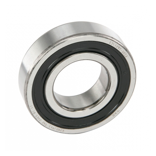
Q: What do the part numbers like 6000, 6200, and 6300 series signify?
A: Part numbers such as 6000, 6200, and 6300 series indicate specific types and sizes of spindle bearings. These numbers help in identifying the dimensions and load capacities suitable for various applications like motor vehicles, dirt-bikes, and watercraft.
Q: What should I consider when selecting a spindle bearing for replacement?
A: When selecting a spindle bearing for replacement, consider factors such as the axial load capacity, clearance, and compatibility with your machinery. Reviewing the spindle bearing size chart will help ensure you choose the correct replacement.
Q: Are spindle bearings in the 6300 series suitable for textile applications?
A: Yes, spindle bearings in the 6300 series can be suitable for textile applications, depending on the specific requirements and machinery involved. It is advisable to consult the size chart and contact our customer support team for detailed guidance.
Q: How do I determine the right spindle bearing for all-terrain vehicles (ATVs) and watercraft?
A: To determine the right spindle bearing for ATVs and watercraft, refer to the spindle bearing size chart and consider factors like load capacity and environmental conditions. Bearings suitable for these applications often include those in the 6000 and 6200 series.
Q: Can you explain the terms “quadplex bearing pairs” and “triplex” in the context of spindle bearings?
A: Quadplex bearing pairs and triplex refer to specific arrangements of spindle bearings used to handle higher loads and improve performance by distributing forces more evenly across multiple bearings.


UCTH213-40J-300 with Setscrew(inch)
CNSORDERNO: Normal-duty(2)
TOGN: UCTH213-40J-300
SDI: B-R1/8
SD: 2 1/2
UCTH212-39J-300 with Setscrew(inch)
CNSORDERNO: Normal-duty(2)
TOGN: UCTH212-39J-300
SDI: B-R1/8
SD: 2 7/16
UCTH212-38J-300 with Setscrew(inch)
CNSORDERNO: Normal-duty(2)
TOGN: UCTH212-38J-300
SDI: B-R1/8
SD: 2 3/8
UCTH212-36J-300 with Setscrew(inch)
CNSORDERNO: Normal-duty(2)
TOGN: UCTH212-36J-300
SDI: B-R1/8
SD: 2 1/4
UCTH211-35J-300 with Setscrew(inch)
CNSORDERNO: Normal-duty(2)
TOGN: UCTH211-35J-300
SDI: B-R1/8
SD: 2 3/16
UCTH211-34J-300 with Setscrew(inch)
CNSORDERNO: Normal-duty(2)
TOGN: UCTH211-34J-300
SDI: B-R1/8
SD: 2 1/8