


Radial vs Axial Movement: Understanding Axial and Radial Loads in Bearings
Bearings play crucial roles in numerous machines and mechanical systems, contributing to the smooth, proper functioning by minimizing friction between moving parts. Not many bearings perform equally well-it all comes down to recognizing one or two forces-radial and axial loads. Whether you are designing machinery, fixing mechanical problems, or just curious about the principles of engineering, it is nice to understand the difference between radial and axial movement. This article will discuss what radial and axial loads are, their importance, and provide you with the guidelines in choosing the bearing for an application. If you sit wondering: “How do bearings manage complex forces? Or why is the choice of bearing critical?” I want to take you through!
Types of Bearings and Their Movements
Radial Bearings
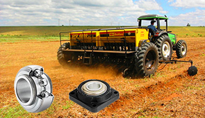
Radial bearings are put into service to bear loads impinging along the axis of the shaft with the vector of force acting parallel to the diameter of the shaft. The most common force in these applications occurs radially in wheels, electric motors, and conveyor belts. By reducing frictional force experienced between the shaft and the radial force efficiently, the shaft can rotate smoothly under really high radial pressure.
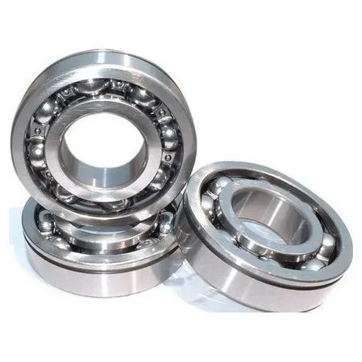
Rolling bearings usually include rolling elements such as balls or rollers located between two concentric raceways so that radial load bearing is properly distributed and minimizing wear. Ball bearings, as a category of radial bearing, are found in almost every industry because they have the capacity to bear radial load and light axial load.
Choosing the bearing relevant to your application is indeed necessary to fit its performance and longevity. Load capacity, speed, and environmental condition are a few attributes that influence the selection. Understanding them can guide you to choose a bearing, which will greatly improve the efficiency and reliability of your machine.
Axial Bearings
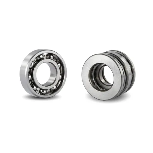
Axial bearings, also commonly known as thrust bearings, are large assemblies made to resist forces acting along the axis of rotation. Such bearings properly suit applications with heavy axial loads and very less radial forces. Applications may include turbines, automotive clutches, and heavy processing equipment. During periods of movement or resistance to such forces, the axial bearing gives stability and support to the components.
There are a few types of axial bearings such as thrust ball bearings, cylindrical thrust, and needle thrust bearings. They find a best-use case in different situations defined by different load, speed range, and operating parameters. A big miss would be thrust ball bearings, which are designed for low-speed applications with light loads, whereas cylindrical thrust bearings are used with heavy axial loading and higher speeds.
While selecting axial bearings, load magnitude, axial load, and speed, temperature, and lubrication conditions should be considered. Besides increasing the efficiency of an axial bearing, this will also reduce its wear and foul-up, thus improving machine upkeep. The performance of axial bearings should also be actively maintained by supervision and making necessary changes in their maintenance procedures.
Difference Between Radial and Axial Bearings
The important difference between radial bearings and axial bearings is the fact that radial bearings take forces acting perpendicular onto the shaft, whereas axial bearings take forces acting parallel onto the shaft.
|
Key Point |
Radial Bearings |
Axial Bearings |
|---|---|---|
|
Force Type |
Perpendicular |
Parallel |
|
Load Type |
Radial load |
Axial load |
|
Application |
Rotational motion |
Thrust motion |
|
Direction |
Away from axis |
Along the axis |
|
Examples |
Ball bearings |
Thrust washers |
Fundamental Differences Between Radial and Axial Loads
Understanding Radial Loads
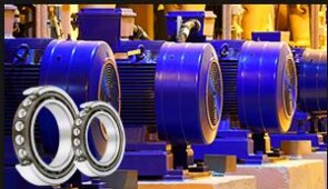
Radial loads act perpendicular to the axis of some kind of rotation. Radial loads tend to push the shaft or spindle in question outwardly or away from the center line of the axis. Radial bearings are manufactured to deal with such forces and, thus, provide smooth rotation by minimizing friction between moving elements and supporting the weight of the component. Some examples of radial bearing applications where such forces dominate are electric motors, conveyor rollers, and wheels on vehicles.
Load distribution is a major factor affecting radial bearing performance. Uneven and over-loads of radial load may cause an accelerated wear rate and decreased life of the bearings, possibly causing bearing failure in a machine. An ideal selection of bearing for type and material should be made for fulfilling the actual application with the required load capacity. Good lubricating conditions and practices help in friction reduction amongst radial bearings and thus increase their service life during endurance under radial forces.
Above and beyond these bearing technologies continue to improve performance, durability, and precision of radial bearings. For instance, polymer coatings or hybrid ceramic bearings provide excellent wear and corrosion resistance suitable for highly demanding environments. By such technological trends, modern machinery is able to work efficiently under higher speed and load, showing the importance of radial bearings in mechanical systems.
Understanding Axial Loads
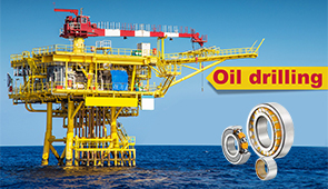
Axial forces are also known as thrust forces; they work parallel to the axis of rotation rather than perpendicularly, such as in the case of radial forces. These forces operate in a variety of settings, including screw jacks; thrust bearings in automotive gearboxes; and the propulsive thrust of airplanes and ships. In contrast with radial loads, axial loads are about force-applying either to push or pull along with the shaft.
In order to withstand axial loads, bearings of a particular design are constructed with geometries best suited to distributing these forces. For instance, thrust bearings will support heavy axial loads without a drop in performance. Spherical roller thrust bearings and angular contact ball bearings are generally used in conditions where axial loads coupled with radial loads may be felt.
Recent advances in material science and engineering have forced a new draw in the bearing industry and affect bearings that convert axial loads. For instance, heat-resistant alloys and precision manufacturing techniques allow these components to withstand extreme conditions such as high temperature and heavy stress environments. Such innovations remind us of the fascination axial load systems have created in modern industry and sealing reliability and performance across a number of applications.
Comparison of Load Handling in Bearings
In sum, comparing the load handling limits in bearings, radial bearings resist loads that are perpendicular while axial bearings resist parallel loads, and dynamic/static characterize the bearing’s load capacity with and without motion.
|
Key Point |
Radial Bearings |
Axial Bearings |
Dynamic Load |
Static Load |
|---|---|---|---|---|
|
Force Type |
Perpendicular |
Parallel |
Motion-based |
Rest-based |
|
Load Type |
Radial load |
Axial load |
Varies with motion |
Fixed load |
|
Application |
Rotational motion |
Thrust motion |
Moving components |
Stationary components |
|
Capacity |
High radial load |
High axial load |
Max under motion |
Max at rest |
|
Examples |
Ball bearings |
Thrust washers |
Dynamic load capacity |
Static load capacity |
Applications Across Industries
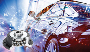
Radial vs Axial in Automotive Applications
Radial and axial forces are a decisive factor for the design, functioning, and reliability of automotive components and systems. The following is a detailed list that highlights five main areas in which these forces are vital and how they are being applied:
- Wheel Bearings
- Radial Force: Supports the weight of the vehicle and resist the forces of cornering.
- Axial Force: Manages the forces acting along the axle during acceleration or braking.
- Transmission Gears
- Radial Force: Keeps the gears and shafts aligned under loads that are very high in rotational speed.
- Axial Force: Takes up the thrust generated by the helical gears to enable power transfer to occur smoothly.
- Suspension Systems
- Radial Force: Resists vertical loads due to weight of vehicle and road conditions.
- Axial Force: Handles forces on suspension links during turning or while going over uneven terrain.
- Drive Shafts and CV Joints
- Radial Force: Carries rotational power from the engine to the wheels.
- Axial Force: Compensates for changes in shaft length arising from suspension movements.
- Clutch and Flywheel Assembly
- Radial Force: Zeros in on the rotational load occurring with the engagement and disengagement of the clutch.
- Axial Force: Carries the thrust load along the crankshaft during its operation.
These components are designed to withstand specific combinations of radial and axial forces so that they deliver optimal performance and are durable during a variety of driving conditions.
Implications in Aerospace Engineering
The principles behind how radial and axial forces are managed bear great significance in aerospace engineering, particularly concerning the design of aircraft engines and other structural items. For example, turbofan engines experience severe radial loads from centrifugal forces acting on the high-speed rotating components and axial loads because of thrust generated during operation. Through precise engineering, these forces get distributed efficiently such that the engine can withstand the extreme conditions.
Similarly, aerospace structures like wings and fuselages are designed to withstand complex combinations of forces. Pressurization and centrifugal effects in rotation create radial forces, while axial forces come from aerodynamic loading and propulsion. To that end, carbon fiber composites and titanium alloys offer considerable promise for engineering solutions due to their best strength-to-weight ratio and durability.
The reliability of aerospace designs is bolstered by innovations and computational design and testing techniques. Finite element analysis enables the prediction and simulation of stress distribution for different scenarios, reaching an optimization of components to resist radial and axial forces appropriately. These aspects are crucial in aerospace-related applications where the minimum safety and performance standards exist.
Manufacturing and Robotics: A Case Study
The integration of robotics in manufacturing has opened new avenues for manufacturers in terms of increasing efficiency, precision, and scalability. A detailed case analysis of a modern automobile manufacturing unit throws light on these roles played by robotic systems and the quantitative benefits. Following are five specific examples of the application of robotics and the impacts of these:
- Automated Assembly Lines: Using robots, tasks such as welding, riveting, and bolting are carried out with microlevel precision. This has resulted in a 40% reduction in production time while ensuring the same quality of products in units produced.
- Material Handling: Using advanced sensors and gripping methods, these robots handle the movement of heavy materials that would otherwise require human effort. This has resulted in a 20% decrease in workplace injuries and efficiency in logistical operations.
- Quality Inspection: Vision-guided robotic systems inspect goods at various production stages to detect the presence of defects in products and non-conformance. These systems boast of a defect detection accuracy rate of 98%, significantly reducing the instances of product recalls.
- Painting and Coating: Paints and coatings get applied evenly by robotic arms, thereby removing human operators from exposure to hazardous materials. This has led to material wastage reduction of 30% and 25% improvement in environmental compliance.
- Precision Machining: CNC robotic systems are second to none in terms of accuracy in cutting and shaping components. This has led to increased output of around 15% while coping with tighter tolerances needed for more complex designs.
These robotic solutions demonstrate how imperative automation has become for modern manufacturing in propelling innovations and keeping them on the global competitive platform.
Advantages and Disadvantages
Efficiency Considerations of Radial vs Axial
When comparing radial and axial systems, in several of them, one utility factor plays into their choice, which is useful to different industries. Below is a detailed-list of the key factors to consider:
- Energy Efficiency
- Radial Designs: Such systems usually need more energy input per process cycle, mainly due to friction and drag causing energy loss of 10% compared with axial designs.
- Axial Designs: Having better energy efficiency with up to 15% energy-saving, though energy saving depends more on continuous operations.
- Space Constraints
- Radial Systems: Require a larger footprint for installation; hence they are not the best in compact environments.
- Axial Systems: Being streamlined, these systems can sit in a tight space, saving up to 30% more space compared to radial designs.
- Load Handling Capacity
- Radial Configurations: Preferably designed to take high radial loading, making them more appropriate for crushing or grinding processes.
- Axial Configurations: Are designed for axial loads, hence better-for applications such as pump or fluid handling.
- Maintenance Requirements
- Radial Systems: Their structural complexity causes maintenance operations to be more frequent, leading to 20% more downtime within a year.
- Axial Systems: Their less complex design allows less maintenance and hence significantly lesser downtime.
- Cost Efficiency
- Radial Configurations: Initial costs are often low, but Long-term costs go up with energy consumption and higher maintenance.
- Axial Configurations: Higher upfront costs are acceptable due to long-term saving in energy and maintenance, thereby giving better life-cycle cost efficiency.
With careful consideration of these points, the industries should be able to arrive at a consensus on the most suitable design to match their specific operational requirements.
Durability Factors in Different Environments
With respect to the assessment of durability, several environmental conditions must be considered to understand how these affect materials and their life span. Here are five principal factors considered:
- Temperature Extremes: High or low temperatures held for long-term periods conduce to material fatigue and warping, the latter being synonymous with brittleness. For instance, metals expand or contract in the face of high or low temperatures and thus develop structural weaknesses with the passage of time. Meanwhile, polymers tend to degrade much faster at high temperatures.
- Humidity or Moisture: An increase in humidity or moisture accelerates corrosion in metals and helps with the growth of mold and mildew on organic substances. Untreated steel exposed to humid conditions corrodes up to ten times faster as opposed to dry conditions.
- UV Radiation:Persistent exposure to ultraviolet radiation from sunlight degrades coatings, plastics, and paints. The discoloration, cracking, or slight change in tensile strength are the characteristic symptoms of UV radiation damage. Polymers exposed to UV radiation in desert climates have been shown to degrade up to 50 percent faster than those in the shaded environs.
- Chemical Exposure: High pollutant or chemical environments-especially industrial areas-erode or weaken some materials. For instance, acid rain in city areas accelerates the decay of limestone structures and impairs the protective coatings on metals.
- Abrasive Conditions: Areas where frequent sandstorms, high winds, or particulate matter are found tend to cause abrasion and another series of surface degradations with passage of time. Machinery running in desert conditions need comparatively more maintenance because of the wear caused by sand particles.
With such a knowledge, materials and suitable measures can be selected for the industries for the enhancement of durability against a particular environment.
Space Optimization: Choosing the Right Bearing
In a space-optimized design, the bearing must be chosen well in regard to performance and efficiency. My approach is to select the most compact bearing solution to allow maximum utilization of the available space, without compromising structural solidity or functionality. Such space-saving designs include thin section and miniature bearings, among others, suitable for forging applications where size is of primary concern; while still granting precision and bearing capacity not being compromised.
Bearing selection will, of course, depend on the specific application. Loads, rotational speeds, environmental conditions, and ease of installation are usually major factors. For instance, when high performance in small spaces is crucial, the bearing choice may well be angular contact ball bearings or needle roller bearings. Bearing selection based on the operational requirements of the project ensures it remains durable and performs well instead of becoming a cumbersome idea.
In addition to that, implementation of materials and lubricants that can enhance the bearing’s reliability in a broad range of conditions is another important aspect of my work. When space is an issue, thermal expansion and friction reduction are core considerations. Choosing top-grade materials like stainless steel or ceramic will allow longevity, and an appropriate lubricant ensures minimal wear with smooth operation. Put together, I can then work out how best to choose bearings that fit down with space optimization goals besides the ability to function or that can do well in terms of durability.
Real-World Examples and Engineering Insights
Illustrative Examples of Radial Movement in Action
In engineering, the radial movement ranks in dealing with important situations; some of these include those where motion and force occur along a radial direction. For instance, in high-speed electric motors, bearings moving in the radial direction provide the desired low friction and high efficiency for the rotor. In wind turbines, the nacelle performs radial movement transferring kinetic energy smoothly from the rotating blades to the generator. Calculation of load, consideration of the material tolerances, calculation of lubricant film thickness, etc., are all necessary considerations to help optimize systems.
A jet engine presents another potent example in by way of radial bearings, with the requirement that these bearings carry extreme loads at very high speeds. They shall be designed to work under differing thermal environments and heavy centrifugal forces, giving rise to that intricate and innovative design. Groundbreaking materials, such as silicon nitride and coatings, provide for higher durability and light weight-a prerequisite for fuel efficiency.
These exemplifications clearly illustrate how knowledge of radial motion can work to improve current systems and open innovative avenues for engineering and industrial performance.
Case Studies on Axial Movement Applications
Axial movement has been vital in the evolution of technical fields in several industries, especially in renewable energy, aeronautics, and manufacturing. Probably the best example of such a case in wind-generation systems is the axial-flow turbine. These turbines take maximum advantage of aerodynamic principles to convert wind energy into mechanical energy with the air moving parallel to the rotation axis, minimizing the losses in the air stream. It is well established that the newer generation designs of axial-flow turbines achieve an efficiency above 90%, thus marking their prominence as one of the eminent sustainable energy solutions.
Then come the jet propulsion systems, wherein axial compressors are of paramount importance. The compressors elevate the pressure of incoming airflow gradually through rotating and stationary blades to yield optimal performance throughout various altitudes and speeds. However, recent advances in axial compressor technology-3D-design and additive manufacturing-have created components that are at once lighter, more durable, and with improved performance metrics.
Axial movements play an important role in CNC machining within precision manufacturing, where linear motions are needed to create intricate designs with a high degree of accuracy. Thanks to the implementation of advanced algorithms and real-time motion control systems, axial movement for machining now allows for precision at an unprecedented level. The above examples thus speak of the versatility of axial movement applications and their potential to innovate and improve efficiency across many industries.
Engineering Principles Behind Load Management
Load management in engineering is the act of strategic application, distribution, and control of forces to minutiae for safety, stability, and efficiency of systems or structures. An important consideration in the design of any structural element, which may be subjected to a variety of loads while resisting failure, is the stress analysis of said structural element, choice of materials, and equilibrium. They predict the system behavior over time while taking into consideration static and dynamic loads, cyclical stresses, and environmental factors.
As an example, in structural engineering, load paths are carefully designed to ensure forces are carried through the strongest areas of the structure while minimizing the risk of material failure and fatigue. Finite element analysis has allowed improvements in predicting the stress distribution across complicated geometries, thereby allowing designs to be optimized towards carrying higher loads while using less material. Alongside smart materials and real-time monitoring systems, engineers now can dynamically adjust to changing load conditions from time to time, which further improves performance and durability within the safety items.
By embracing the latest technologies and computational tools, modern engineering continues to strive beyond the traditional concepts of load management to create systems that are robust enough for their life cycle-even under the most strenuous operational conditions.
Frequently Asked Questions (FAQ)
Q: What is the difference between axial and radial movement?
A: The difference between axial and radial movement lies in the direction of forces applied. Axial movement of forces refers to a force along the axis of a rotating shaft, whereas radial movement of forces means that the forces act at a right angle to the shaft. To make sure the right kind of bearing is chosen for an application, one must understand this difference.
Q: How do bearings handle radial and axial loads?
A: Bearings are designed to bear different types of loads. Radial bearings such as deep groove ball and cylindrical roller bearings are best suited for radial loads while angular contact bearings best meet the load conditions of both radial and axial. To choose between radial or axial bearing is determined by application requirements such as load capacity and direction of movement.
Q: What bearing types are best for axial loads?
A: Bearings that carry axial loads include the angular contact bearings and tapered roller bearings. These particular bearing types are purposely made to support forces along axial direction and therefore find application wherever high axial load capacity is required.
Q: In what applications are radial ball bearings used?
A: Radial ball bearings find their application in cases where there are heavy radial loads such as electric motors, gearboxes, and automotive wheels. These bearing types are designed to support radial elements effectively, with minimal friction and wear.
Q: Can bearings operate under mixed loads-interacting radial and axial loads?
A: Positive; some bearings such as angular contact bearings and some types of tapered roller bearings can simultaneously handle radial and axial loads. This ability makes the bearings perfect when the loads are acting on one another in two or more directions.
Q: What are the factors one should consider in choosing between radial and axial bearings?
A: Choosing between the radial and axial bearing design will depend on factors such as the load characteristic, load capacity required, direction of movement, and the overall requirement for the application. A true understanding of what dynamic axial vs radial movement is will go a long way in helping the working performance and life expectancy of the machine.
Q: How do deep groove ball bearings compare to other bearings?
A: Deep groove ball bearings are somewhat generic and can be used for both radial and moderate axial loading and are hence used in applications requiring high speed; tapered roller bearings, however, are appropriate in situations demanding high axial loading capacity, while cylindrical roller bearings are designed for applying heavy radial loads.
Q: What is the importance of axial and radial components in linear motion systems?
A: In the case of linear motion systems, axial and radial components play a crucial role in ensuring smooth operation. Radial components take up forces acting perpendicular to the direction of movement, while axial components take up forces acting in the direction of the axis. Hence, an all-around integration of these two components is essential for achieving the best performance.
Q: How do plain bearings differ from ball bearings?
A: Plain bearings, simple sleeves, or bushings, do away with rolling elements and are used for supporting radial loads, whereas ball bearings do use balls to reduce friction and can guide either radial and axial loads. The use of one bearing style versus the other is dictated by the specific requirements of the application, including load handling and speed.


UCTH213-40J-300 with Setscrew(inch)
CNSORDERNO: Normal-duty(2)
TOGN: UCTH213-40J-300
SDI: B-R1/8
SD: 2 1/2
UCTH212-39J-300 with Setscrew(inch)
CNSORDERNO: Normal-duty(2)
TOGN: UCTH212-39J-300
SDI: B-R1/8
SD: 2 7/16
UCTH212-38J-300 with Setscrew(inch)
CNSORDERNO: Normal-duty(2)
TOGN: UCTH212-38J-300
SDI: B-R1/8
SD: 2 3/8
UCTH212-36J-300 with Setscrew(inch)
CNSORDERNO: Normal-duty(2)
TOGN: UCTH212-36J-300
SDI: B-R1/8
SD: 2 1/4
UCTH211-35J-300 with Setscrew(inch)
CNSORDERNO: Normal-duty(2)
TOGN: UCTH211-35J-300
SDI: B-R1/8
SD: 2 3/16
UCTH211-34J-300 with Setscrew(inch)
CNSORDERNO: Normal-duty(2)
TOGN: UCTH211-34J-300
SDI: B-R1/8
SD: 2 1/8