How Does a Cam and Follower Work: Understanding the Cam and Follower Mechanism
The cam and follower mechanism is a fundamental component widely used in mechanical engineering and design, playing a critical role in converting rotary motion into linear motion or vice versa. Whether found in automotive engines, industrial machinery, or intricate clockwork systems, this mechanism has become an essential element in ensuring precision and efficiency across a variety of applications. But how exactly does this interplay between the cam and follower function, and why is it so pivotal? This article will provide a detailed exploration of the science and mechanics behind the cam and follower system. By the end, you’ll have a clear understanding of how this ingenious mechanism operates, its core principles, and the practical significance it holds in modern engineering.
Types of Cams and Followers
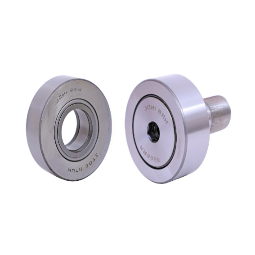
Cylindrical Cam
Cylindrical cam types have a working surface wrapped around the cylinder. The follower moves according to the profile cut on the surface of the cylinder, which is usually intended to realize specific motion requirements. Cylindrical cams are frequently employed in machines where linear or oscillatory motion of the follower is desired, thus converting rotary motion into controlled linear displacement.
The foremost attractive feature of cylindrical cams is their ability to handle complicated motion profiles, all with very high accuracy. This makes them suitable for high-performance applications such as automated manufacturing equipment, textile machinery, and some internal mechanisms of engines. The cylindrical shape offers a forever smooth operation, reducing wear and making the motion repeatable for long periods.
In brief, cylindrical cams constitute very important components in places where motion is to be controlled reliably and accurately. Utilizing their capability to handle complicated motion paths, engineers find great opportunities in providing designs that are useful for the longevity and smooth operation of a system. Hence, cylindrical cams remain a vital link in modern engineering.
Disc Cam
The disc cam, sometimes referred to as a radial cam, converts rotary motion into an axial or oscillatory motion depending on the reception of its follower. The profile of the cam is normally that of a flat disc, or else it may be contoured, and its edge is always kept in contact with the follower. This construction design makes disc cams suitable for high-speed applications and offers very precise control over the motion of the follower. Their relative simplicity makes them widely used in many mechanical systems, including printing presses, flow control for valves, and automated machinery.
The main advantage a disc cam has is its ability to produce very complicated non-linear displacements inside a limited space. An engineer could design the cam profile to give the follower movements comprising dwell, rise, and return, all very precise to be synchronized with other parts of the system. This versatility makes the disc cam highly reliable for repeated, predictable applications, for example, in manufacturing and process automation.
Disc cams are generally fashioned from very hard materials, such as steel or alloys, to withstand the repetitive mechanical abuses they undergo. For ensuring that the design achieves maximum efficiency and long life, proper lubrication must be provided, wear at the contact surfaces between cam and follower minimized, and accurate alignment of the follower maintained. The simplistic design and immense functional versatility have rendered the disc cam so important in the field of modern-day engineering that it has become an indispensable element in every mechanism that needs good control of motion.
Drop Cam
The term drop cam refers to a particular kind of cam mechanism, mainly used where a very precise vertical motion is necessary. The mechanism is required to drop or lower a follower member very rapidly over a given distance, which gets the pressing, cutting, or stamping actions done within that time. The cam profile is designed to control the descent of a follower with precision, stability, and minimum wear. The manufacturers, in general, use these drop cams in mechanisms, such as presses, for repetitive operations.
A drop cam design normally comprises a heavy-duty cam profile with a well-matched follower. The profile of a cam defines the motion characteristics; hence, the drop must be smooth with no interruption whatsoever. The follower is exactly aligned to minimize friction and wear, thereby enhancing the operational efficiency and the operating life of the entire system. A provision for an adequate lubrication system and materials for manufacturing, such as hardened steel or high-strength alloy, must be considered for durability under high-stress conditions.
The drop cams find their applications in the manufacturing industries in various ways when used for transferring motions in a very simple yet very effective manner. They automate the vertical movements precisely, thereby increasing productivity while reducing human errors. Drop cams play a vital role in providing high-speed assembly lines or low-cycle production processes in the control of reliable, repeatable, and efficient motion. Their huge demand on the industrial front is proof enough of their importance in modern industrial systems.
How the Cam and Follower Mechanism Operates
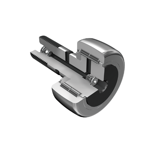
Step-by-Step Walkthrough
- Cam Design and Shaping: The design or profile of the cam governs the motion output imparted to the follower. Common profiles include circular, eccentric, and heart cams, with each suited to a particular application. The engineers select the cam profile depending on the desired motion of uniform rise, dwell, or rapid return.
- Follower Type Selection: Followers are classified into various types concerning their motion and the nature of their surface of contact. For instance, a roller follower will tend to minimize friction using rolling friction, whereas a knife-edge follower must be very precisely machined to allow it to glide smoothly but tends to wear away at the contact surface. The choice depends on the speed, load, and stresses involved during use.
- Cam and Follower Assembly: After the cam and follower have been selected, they are then assembled into their mechanical environment. The alignment procedure must ensure constant contact between the follower and the cam surface during operation, maintained by springs or gravity to avoid any possibility of slipping.
- Input Motion Transmission: The cam is coupled with a prime mover, like an electric motor, which imparts the cam with a rotary or reciprocating motion. The input speed is chosen to set the timing and the output motion.
- Displacement of Output Motion to the Follower: The follower displaces to follow the cam profile and rotation. During the rise, for example, the roller follower transforms the rotary motion of the cam into a vertical displacement. This step is defined by the theoretical motion diagram at the design stage.
- Output Motion Analysis and Correction: The output motion is analyzed for conformity with requirements. Precision measuring instruments, such as dial indicators or encoders, are used to measure displacement, velocity, and acceleration profiles, and if any deviation is observed, then correction of the design or alignment is implemented.
The advancement in material science and precision machining helped further the implementation of cam and follower mechanisms into automated systems. Current computational tools like CAD and FEM are implemented to simulate performance under various load conditions to guarantee maximum reliability and efficiency. This serves as an advantage in extending the application horizon of cam-governed systems in industries ranging from automotive manufacturing to robotics.
Common Configurations
The wide array of cam and follower mechanisms is arranged in many arrangements to suit the motion requirements, load capacities, and application environments. Among the most common types are radial cams, cylindrical cams, conjugate cams, and disk cams. The follower types are knife-edge, roller, flat-faced, or spherical. Radial cams are perhaps the most widely used units due to their compact arrangement and precise motion output, while cylindrical cams are typically chosen when there is a need to create linear or rotational motion along an axis. Conjugate cams find specialized use where there is a need for smooth and synchronized movement of two followers and are mostly used in high-performance machinery applications.
Roller followers, in contrast, are favored in high-speed and high-load applications because they reduce friction and increase durability. Flat-faced followers, in comparison, offer a simple design generally used in light and medium load applications. Knife-edge followers, while generally constrained to low loads, yield high precision.
Together with detailed computational models, such arrangements allow us to predict issues such as stress distributions, wear rates, and the best material for actual application. This knowledge-driven method enables the configurations to best serve their purpose while the threat for failure points is kept to a minimum.
Applications of Cam and Follower Mechanisms
Automotive Engineering
Cam-follower mechanisms operate at the confluence of automotive engineering, especially in the design of reciprocating internal combustion engines. They are involved in valve timing, which must be carefully controlled concerning intake and exhaust valves; any change in this would directly affect the efficiency of the engines, the fuel or any other combustible commodity used, and their emission levels. Using advanced simulation tools, the engineer will have some scope for analyzing the dynamic behavior of cam-follower mechanisms for diverse operating conditions and finally make certain the performance is optimized in terms of lift profile, angular velocity, contact pressures, and forces.
Modern automotive engine systems have grown in flexibility and efficiency largely owing to advancements in VVT, electronically actuated cams, and sensors. These make the engine capable of fighting against emission standards and keeping up the highest possible power at any speed and load we are dealing with. Developments in materials have also helped reduce wear and friction in cam and follower systems, enhancing life and reducing maintenance.
The automotive field keeps tweaking the mechanisms utilizing modern-day predictive modeling checked against experimental validation so that the mechanisms stand in line with the required performances set down by environmental laws.
Manufacturing Processes
Modern manufacturing processes in the automotive industry combine precision engineering with the latest technological advancements to ensure maximum efficiency and quality. In manufacturing engine components like cams and followers, the process largely involves CNC high-precision machining. The CNC fine-tunings allow manufacturing of parts with extremely tight tolerances, truly fine-tuning performance, and reducing variability in operation.
Materials selection is equally advanced, tuned in alloys and composite materials to endure high temperatures and stresses in engine operating conditions. Powder metallurgy, for instance, is another favorite in manufacturing difficult parts due to its capability to yield uniform microstructures that promote durability.
Automation and robotics offer ease to various phases of production, from assembly lines to quality control checkpoints. Automated inspection systems employ machine vision and laser measurements to identify defects at the microscopic level, ensuring components conform to stringent specifications.
Another growing area of importance is additive manufacturing (3D printing), especially for prototyping and short production runs. It allows hollowed manufacturers to speedily fabricate and test design iterations, saving much lead time and thus less material wastage.
Increased efficiency is reached by coupling predictive modeling tools with manufacturing software so designs are tested in a virtual environment even before being made physically. This helps to curb errors while making production align with environment regulations, thus supporting sustainability in great performance.
Robotics and Automation
Robotics and automation continue to transform manufacturing processes by instilling precision, replication, and efficiency. The very advanced robotic systems, together with machine learning algorithms, observe the equipment’s efficiency in real time, predict the impending failure of components, and thus drastically reduce downtime-related costs and repair expenses. Until now, automation has been applied to cobots working alongside human operators to enhance flow and reduce the physical load on human workers.
Further integration of industrial automation with the Internet of Things has brought more optimization into the production environment. On the manufacturing floor, IoT-connected devices collect a massive amount of data that aids intelligent decision-making and dynamically adjust production parameters. For example, in conjunction with data analytics, these systems optimize assembly lines for energy efficiency, thereby lowering operating costs without compromising on quality.
Emerging areas such as robotic process automation expand automation into brook areas such as supply chain management, wherein inventory tracking, order processing, and demand forecasting may be handled with minimal human intervention. So, the mixture of robotics, automation, and data-driven technologies is actually creating hyper-efficient industrial ecosystems while pushing the production’s scalability and innovation elevation.
Comparative Analysis
Cam and Follower vs. Other Mechanisms
It is worth comparing the cam and follower linkages with cranks, levers, gears, and belts to determine their motion transformation capability, their greater complexity, and a wide range of applications.
|
Aspect |
Cam & Follower |
Crankshaft |
Linkages |
Gears |
Belt Drives |
|---|---|---|---|---|---|
|
Conversion |
Rotary to Linear |
Rotary to Rotary |
Linear/Rotary |
Rotary |
Rotary |
|
Design |
Moderate |
High |
Simple |
Moderate |
Simple |
|
Accuracy |
High |
High |
Medium |
High |
Low |
|
Uses |
Engines, Toys |
Engines |
Robotics |
Machines |
Conveyors |
|
Lifespan |
Medium |
High |
Medium |
High |
Low |
Advantages and Disadvantages
Advantages
- Great Precision and Accuracy: Cam and follower mechanisms display superior precision in transmitting motions, thus affording the right control to other components of machinery. This characteristic finds value in applications such as automation, whereby minimal deviation is necessary.
- Flexibility in Motion Profiles: The cam can be designed under different motion profiles, such as uniform motion, oscillatory motion, or non-uniform motion. This makes it more convenient for adoption in other industrial applications.
- Small in Size: Cam and follower systems usually come much smaller as compared to a system comprised of gears or chains and are thus ideal for space-constrained setups. The compactness contributes to an overall reduction in system weight, thereby making it simpler to install in machines.
- Less Maintenance: Since the mechanism is simpler in assembly and usually has fewer moving parts compared to other mechanisms, periodic maintenance will tend to be less, increasing downtime of the operation and thereby life-cycle cost.
- Smooth and Continuous Operation: The interaction between the cam and its follower is capable of providing smooth and continuous operation, thereby reducing vibrations and increasing the overall system efficiency and longevity.
Disadvantages
- Wear and Tear: The continuous interaction between the cam’s surface and the follower would induce some wear and tear if left unchecked, especially in high-load applications. This demands periodic inspection with eventual replacement of the parts.
- Less Load Bearing Limit: Cam and follower mechanisms generally come to bear less load than gear systems, and this limits their use in applications requiring heavy-duty.
- Higher Manufacturing Complexity: The precision machining required for the manufacture of most custom cams can be quite complex and expensive, thereby increasing the production cost right from the onset and tending to limit design flexibility.
- Greater Friction Losses: The cam and follower interaction involves sliding friction-this generates energy losses and inefficiency; hence, it becomes paramount to have lubrication systems put in place.
- More susceptible to misalignment: Precise alignment of the cam and the follower is imperative for best performance. This means that any misalignment could reduce performance, increase wear, and even cause system failure.
All these advantages and disadvantages must be very well weighed in considering whether a cam and follower mechanism suits a particular application.
Historical Development of the Mechanism
This is one of the many areas that relate to early mechanical design, especially regarding timekeeping and automation. The roots of this mechanism can be traced back to ancient eras, as some form of cam would be embedded inside water clocks to control the flow and hence measure time. By the time of the Middle Ages, the concept of the cam had been further improved to be incorporated into systems of increasing complexity, including automata and early astronomical clocks.
During the Industrial Revolution, the cam and follower mechanism was at the foundation of machinery, particularly textile-making machinery, and internal combustion engines. There was considerable advancement during this period in the precision engineering of cam profiles so that motion could be transferred smoothly, and very specific motion patterns could be achieved. To increase the durability and functionality of these mechanisms, innovations were introduced regarding the use of hardened materials and machining processes.
Further sophistication has been lent to the modern cam-follower with computer-aided design (CAD) and numerically controlled (NC) manufacture, permitting the generation of complex cam profiles to exacting specifications. The use of new materials, including advanced alloys and composites, also helps to minimize wear and increase efficiency. Today, the cam and follower mechanism exists in numerous sectors, from robotics to aerospace, reinforcing its profound effect in the whole area of mechanical engineering and adaptability to changing requirements in technology.
Maintenance and Troubleshooting
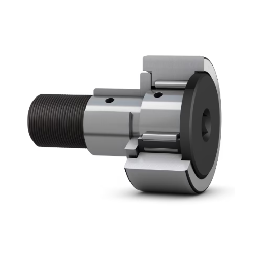
Best Practices for Maintenance
Long-term operational usability and reliability of cam and follower mechanisms demand maintenance as per systematic instructions. Firstly, lubrication should be given all its due emphasis; frictional force acts to degrade the cam and follower surface. Lubricants of good quality should be chosen about the application conditions-for example, loads and temperature. Secondly, inspection should be carried out at specified times so that early indications of fatigue, misalignment, or surface damage might be detected. Visual inspection, combined with the use of precision instruments for checking tolerances, can be utilized for detection.
Also, working conditions cleanliness is very important. Dirt and waste particles or contaminants can expedite the wear process and adversely affect performance. Protective covers or seals should be arranged to overcome such hazards. Alignment has to be checked along with the cam and follower, for improper alignment causes uneven load density and resultant stress and premature failure. Furthermore, if any components appear seriously worn, cracked on the surface, or otherwise damaged, they should be replaced immediately to prevent secondary failure of adjacent components.
These are the best practices that, if embedded in the routine inspection schemes, combined with recent developments in the field of condition monitoring technology such as vibration analysis and thermal imaging, may probably enhance the operational efficiency and life of cam and follower mechanisms and reduce unforeseen downtimes.
Tips for Longevity and Performance
- Material Selection: Considering this is important, as wear, cams, and followers are generally made of hardened steel and alloys with considerable resistance to abrasion and fatigue. Thus, depending upon the requirements, some surface hardening such as carburizing or nitriding may be applied to increase surface hardness and life.
- Proper Lubrication: Thus, infrequent and inconsistent lubrication promotes friction and heating, both of which are causes of excessive destruction of the components. Choose high-performance lubricants according to the operating and working conditions, are load, speed, and temperature, so as to utilize them according to their greatest efficiency and reliability.
- Precision Alignment: Misalignment in cams and followers creates uneven stress distribution; this accelerates wear and lowers efficiency. Proper alignment of different components during installation and their periodic recalibration prevents imbalance, which otherwise can cause early failure.
- Monitoring and Diagnostics: The early signs of failure can be detected by using advanced condition monitoring techniques. Vibration analysis, acoustic emission monitoring, and infrared thermal imaging are some of the techniques to precisely detect anomalies, allowing maintenance and repairs at the appropriate time.
- Loading Optimization: It is very important for the longevity of a cam and follower mechanism to be operated within its given load range. If the system is overloaded, this will cause permanent mechanical damage; if it is kept operating for long periods under excessive load, it will affect the strength of its components.
- Scheduled Maintenance: Carry out systematic maintenance at given intervals related to the specific application and working conditions of a cam and follower system. This must comprise periodic inspection, cleaning, and replacement of parts where wear and damage exceed the permitted level.
By using some of these techniques along with a comprehensive maintenance strategy, operators will be able to promote the maintenance and serviceability of cam and follower systems, keeping costs relatively low with fewer contingencies.
Frequently Asked Questions (FAQ)
Q: What is a cam and follower mechanism?
A: A cam and follower mechanism is a mechanical system that converts rotary motion into linear motion. In this system, the cam rotates, and the follower, which is in contact with the cam, moves accordingly. This transformation is crucial in various applications, such as internal combustion engines, where it aids in opening and closing valves.
Q: How does a cam and follower work in engines?
A: In engines, the cam is used to control the timing of the opening and closing of valves. As the cam rotates, its profile pushes the follower, which moves in a linear path. This motion is crucial for the timing of combustion cycles, allowing for the precise operation of exhaust and intake valves.
Q: What are the different types of cams used in the cam and follower mechanism?
A: There are various types of cams, including cylindrical cams, disc cams, and drop cams. Each type of cam has a unique profile that determines how the follower moves, whether it oscillates, reciprocates, or moves linearly.
Q: What role does the follower play in the cam and follower system?
A: The follower is a crucial component that translates the cam’s rotary motion into linear motion. Depending on the type of follower used, such as a roller follower or a flat-faced follower, the motion of the follower can vary in direction and characteristics.
Q: How does the shape or profile of the cam affect its operation?
A: The shape or profile of the cam directly influences the type of motion produced by the follower. A cam with an irregular shape can produce complex motion patterns, while a cam with a smooth, consistent profile typically leads to predictable linear motion.
Q: What is the significance of the axis of rotation in a cam and follower?
A: The axis of rotation is critical as it determines the pivot point around which the cam rotates. The positioning of this axis affects the follower’s movement and the overall efficiency of the cam and follower mechanism, especially in applications requiring precise motion.
Q: How does friction impact the performance of a cam and follower?
A: Friction can have a significant effect on the performance of a cam and follower system. Excessive friction can lead to wear and tear, impacting the contact area between the follower and cam, which may alter the intended motion and efficiency of the system.
Q: What is the relationship between dwell angle and cam profiles?
A: The dwell angle refers to the period during which the follower remains stationary while the cam rotates. This is particularly important in cam profiles designed for specific applications, such as when the follower needs to pause for a certain duration to ensure proper timing in machinery operations.


