Bearing Fit: Understanding the Importance of Selection for Shafts
Proper bearing fit contributes to the efficiency, reliability, and longevity of rotating machinery. The choice of a proper bearing fit for a shaft demands a nuanced approach based on engineering principles; for instance, load, temperature, or materials might be considered factors. A fit that’s too loose or too tight might cause performance to be affected, wear it prematurely, or those very few times, cause failure mechanically. This article examines the technical details of bearing fit selection, with an emphasis on fitting to ensure performance and avoid expensive downtime. Whether you’re an engineer, burgeoning technician, or business operator, this manual provides you with the necessary genius to decide adequately on put-and-shaft compatibility.
Key Factors to Consider When Selecting the Right Fit
Load Conditions and Their Impact
Load conditions establish an essential criterion while choosing the appropriate fit for a bearing. Bearings may face radial and axial loads, and the effects of the type of load, its direction, and its magnitude have a direct bearing on the accuracy of the fit. Higher and fluctuating loads always need tighter fits in order to prevent any slipping of the bearing against the shaft. Looser fits under such loads would cause fretting corrosion, temperature fluctuation, and early failure. Lighter or constant loads would allow for a looser fit without too much stress during mounting or operation.
Dynamic forces-vibrations, and shock loads-also come into the picture when considering fits, especially if the machine is operating under varying conditions. An interference fit is thereby preferred in such conditions to resist any displacement derived from the frequent change of load or application of external impacts. This way, the bearing remains locked and does not deform through harsh situations. Selection of interference fit is an important consideration since components must be manufactured to close tolerances, for otherwise, assembly problems or damage to parts could occur.
Again, temperature differences must be allowed for when evaluating load cases. Bearings subjected to extreme thermal gradients may undergo the expansion or contraction of material, thus changing their intended fit. Correct material compatibility accounting for thermal gradients is a must for ensuring operational stability and longevity of service. Set in a big way, concerning the load itself, all these factors must be attended to lest there be a failure in the operation, guaranteeing the reliability of industrial use.
Operating Temperatures and Material Properties
The operating temperature plays a big role in how well materials in a system respond and how durable they last. Excessive heat or cold would cause deformation, embrittlement, or fatigue in materials, incurring loss of functionality. Metallic components, at high temperatures, may expand enough to change tolerances and cause misalignments, whereas polymers might soften or degrade and cause premature failure. Such problems dictate the necessity of picking materials that can work with good thermal resistance and stability.
Material properties, such as thermal conductivity, coefficient of thermal expansion (CTE), and thermal endurance, dictate their behavior under varying temperature conditions. When a metal is considered for use in high-temperature environments, the best choices would be stainless steel or titanium for their low CTE and high strength retention. On the other hand, advanced ceramics and composites are considered when insulation and extremely low expansion are requirements. An understanding of these properties ensures an effective frequency between materials and application requirements.
At the same time, when a proper thermal control can be applied through, for example, heat sinks or insulating barriers, it ensures the temperature remains acceptable and thus the integrity of the material is not compromised. Raising a system with adequate materials combined with suitable design approaches will help to achieve operational efficiency and also offer extended service life even if subject to stringent thermal limitations. Failure to evaluate temperature-dependent material property issues correctly could even lead to a reliability question in an industrial scenario.
Tolerance Measurements: Shaft and Housing
Tolerance measurement is tremendously important because it ensures that shafts will fit with housings for proper functioning within a mechanical assembly. The right tolerances allow for proper fits, lessening the potential for mechanical failure, wear, or inefficient operations. The selection of a particular dimension is generally made concerning international systems, such as ISO 286, which defines the dimensional tolerances and the fits for cylindrical parts. These systems provide absolute limits for maximum permitted deviation from the nominal dimension, assuring that the parts can be manufactured with a consistent degree of precision on a repetitive basis.
Shafts and housings are generally tolerated as clearance, transition, and interference fits, depending on their intended application. Clearance fit keeps parts loose, suitable for parts performing relative movements, whereas interference fit is essentially a force fit that holds the parts firmly; for example, heavy assemblies. Transition fit lies between the two, allowing slight resistance but not excessive tightness.
Accurate tolerance measurement is usually carried out by means of highly developed measuring instruments, such as micrometers, calipers, or coordinate measuring machines, depending upon the required accuracy. Using these measuring instruments, the manufacturer rejects shafts and housings outside design tolerances. Most importantly, the acceptance of these measured values assures functioning and also helps in quality retention, thereby leading to reduced wear and tear with time and to safe operation.
Types of Bearing Fits
Interference Fits: Definition and Applications
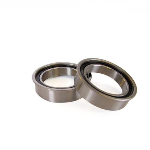
Being the most employed types of mechanical fits, interference fits are also known as press or shrink fits. The external dimension of the shaft is always a trifle larger than the internal dimension of the corresponding housing or bore that is concerned. This very minute overlapping between the mating members forms a solid bond and is in many cases, permanent because the two components come to be compressed during assembly. Herein, interference fits prevent any relative motion of the shaft in the housing and therefore provide a strong mechanical engagement under operating conditions.
This type of fit is best suited for applications operating under high loads and speeds, where slippage or loosening could cause them to fail. Their applications include putting gears, pulleys, and wheels onto shafts and putting bearings under heavy mechanical loads. Alternately, in order to permit quick assembly on the interference fit, the engineer may heat the housing or cool the shaft so as to temporarily reduce the interference.
The interference fit also eliminates the capacity for fretting wear and fatigue caused by minute relative movements at the interface. In any case, utmost care in the calculation of the amount of interference should be exercised. The different considerations would be whether maximum or minimum interference is required, with regard to material, coefficients of thermal expansion, and load requirements, so that excessive stresses are not induced and the integrity of the component is not compromised. ISO and ANSI specifications are good guides to the determination of suitable interference values for a particular application.
Clearance Fits: When to Use
Clearance fits are utilized when primary considerations revolve around ensuring free motion capabilities between mating components without interference. When ease in assembly or disassembly is sought in typical operation, as with slide, pivot, or rotational motion, clearance fits find more application. Also, clearance fits come in handy when systems undergo thermal expansion or plastic deformation, wherein any interference would bring operational failure or enhanced wear.
The choice between clearance fits depends on a variety of aspects, including the functional purposes, the degree of precision expected, and the operational load to which the component will be subjected. In a loose clearance fit, these are used where the less the precision, the better, i.e., very low loads such as those experienced by hinges. In contrast, a close clearance fit would be employed where every contact must be carefully prescribed, such as a shaft in a bearing with controlled tolerances to keep play at a minimum or just enough so that it can function. Standards allow the use of ISO or ANSI classes for tolerances, which makes it easier to determine the clearances needed for a particular industrial requirement.
In addition, advances in materials engineering and manufacturing technologies, such as precision machining methods and advanced metrology tools, have greatly contributed to tighter control of tolerance in clearance fits. With the help of predictive modeling software, engineers are able to simulate operational conditions and ascertain the exact fit needed, diminishing performance problems from arising with age. Ultimately, recognizing the finer details of the operational context, coupled with standardized guidelines, would decide whether and how effective a clearance fit can be in a mechanical assembly.
Transition Fits: Balancing Between Loose and Tight
These fits stand in between a clearance fit and an interference fit and thus provide a versatile solution for applications where exact control of assembly tolerance is desired. Depending on the size variations of mating parts, transition fits permit a little clearance or interference. In this way, an assembly of two components is neither too loose nor too tight, and can be used where certain frictions or controlled alignment or tolerance needs to be experienced in operation.
Another plus for a transition fit is that it offers slight advantages in dealing with minor variations in dimensions that come about during manufacturing processes like machining or forging. Engineers use them in mechanisms with less stringent positioning requirements that are easy enough to put together and take apart. Transition fits appear in gears, couplings, and pulleys where it is important to find the right balance between hold and removal. In doing so, engineers rely on precision metrology tools and quality control processes to ensure the fine tolerances required for transition fit.
With the evolution of new manufacturing and inspection technologies, transition fits have come to achieve an even higher level of precision and reliability through engineering design. Now accompanied by computer-aided design (CAD) and computer-aided manufacturing (CAM) software, precision fitting allows the engineer to plan how parts will interact and further simulate possible shortcomings that could occur during their real assembly on-site. Other updated advanced techniques include laser scanning and automated tolerance analysis, which can provide measurements with micron precision and are extremely valuable in guaranteeing the right fit. These advancements point to the importance of continual incorporation of the latest technologies into engineering practices toward the aim of bettering the performance and operational efficiency of mechanical systems.
Common Challenges in Bearing Fit Selection
Improper Tolerance Measurements
Improper tolerance measurements represent major stumbling blocks in designing and assembling mechanical systems. Bearings, for example, require very precise tolerances for the ultimate performance and durability. A tolerance that is too loose causes the bearing to develop excessive play, which in turn causes noise, vibration, and wear with time. Conversely, too much tightness in the tolerances could place undue stress on the bearing or its housing, causing at least deformation and possibly overheating and premature failure. Conversely, if the tolerance is too tight, it may enforce undue stress upon the bearing or its housing, which is likely to cause deformation as a minimum, and overheating and premature failure at worst. Hence, proper tolerance measurements are very important for establishing the balance between fit and function of engineered systems.
Lack of consideration for thermal expansion and compatibility of materials is one of the major reasons for improper tolerance measurements. Under varying temperature conditions, materials expand or contract at different rates based on the values of their thermal expansion coefficients. This phenomenon must be taken into account by engineers when designing; otherwise, it may lead to misaligned components or compromised fits when under extreme thermal loads in operation. Advanced simulation tools as well as real-time computational modeling have become invaluable in aiding the prediction of these variations and applying suitable design corrections.
Furthermore, outdated digital and manual metrological tools can be another source of error in tolerance measurements. Contemporary engineering disciplines increasingly rely upon digital metrology systems such as laser interferometry and coordinate measuring machines (CMM) to gain unprecedented precision in tolerance measurements. These devices are engineered to sense deviations at the scale of microns and guarantee correction of the slightest variation. The incorporation of such advanced technologies in standard procedures considerably alleviates the perils of improper tolerance measurements that align with the demands of modern mechanical systems.
Thermal Expansion Issues
Thermal expansion has great importance in engineering and manufacturing processes as materials inherently expand and contract with varying temperature conditions. This occurs due to the atomic structure of materials, where the increment of thermal energy causes atoms to vibrate and move away from one another, thereby changing the dimension of the material. Such a property is described by the term coefficient of thermal expansion (CTE), whereas a material differs in CTE. Metals are typically considered to have larger CTEs than ceramics or composites, so in the selection of materials for an application with a thermal environment, mechanical inconsistencies or failures can be avoided.
One of the foremost difficulties imposed by thermal expansion occurs in precision assemblies and critical tolerances. Joining different materials can create big stresses at interfaces in opposition to external constraints: this is often due to mismatched CTEs in bimetallic components or composites. These stresses are capable of inducing warping and fatigue, even structural failure, if they are not considered during the design stage. Thermally-induced expansions in complex assemblies are thus being simulated by advanced simulation tools, including FEA, allowing the engineer to modify the design or add expansion joints to reduce the risks.
To mitigate the problems related to thermal expansion, emphasis must also be placed on environmental controls during the production and operation processes. For instance, in precision manufacturing, temperature and humidity are controlled within narrow tolerances to minimize any risks due to discrepancies in dimensional parameters. Additionally, there are material innovations such as expansion alloys like Invar or Zerodur, which are now increasingly being used in aerospace, optics, and metrology zones. Hence, by using design, material, and controlled conditions, the harmful effects of thermal expansion can be minimized toward system dependability and lifespan.
Misalignment and Its Consequences
In engineered mechanical systems, the misalignment may be due to faulty assembly, depletion of partners through usage, thermal distortion, or consequent inaccuracies during manufacturing. When left unaligned, even by a few micrometers, the involved effects would be cascaded down toward system performance, efficiency, and durability. For instance, in mechanical assemblies, misalignments cause uneven load distribution, premature wear, frictional losses, etc., and these would further cause the failure of bearings, shafts, or certain other critical components. It is essential to address the misalignment fault in the early stages of design and maintenance to avoid the failure’s compounding effects.
With the intent of operation, inefficiency introduced by misalignment makes the whole process very ripple-like. Higher vibrations, increased noise levels, and heat generation could be some of the symptoms observed in the case of misaligned components. Such circumstances not only reduce the life span of parts but also may threaten safety in high-stakes industries like aerospace, automotive, or industrial manufacturing. Hence, energy losses with systems out of alignment would surely be another reason for increased operational costs with passing time, thereby guaranteeing precision at every step of the equipment lifecycle.
The other universal ways to remedy the adverse effects of misalignment include precise calibration, for instance, diagnostic means like laser alignment or vibration analysis. These means can be applied during any assembly or installation to find and rectify such variance behind any medicament for optimum system operational efficiency. Inclusion of design concepts to take into consideration possible misalignments, such as resilient couplings or compliant mechanisms, can boost the capability of a system to absorb minor inaccuracies without affecting its performance. Minimizing or eliminating the impact further ensures reliability and efficiency if an intervention is made at every stage of the design, assembly, or maintenance process.
Industry Applications of Bearing Fits
Automotive Industry: Critical Fit Considerations
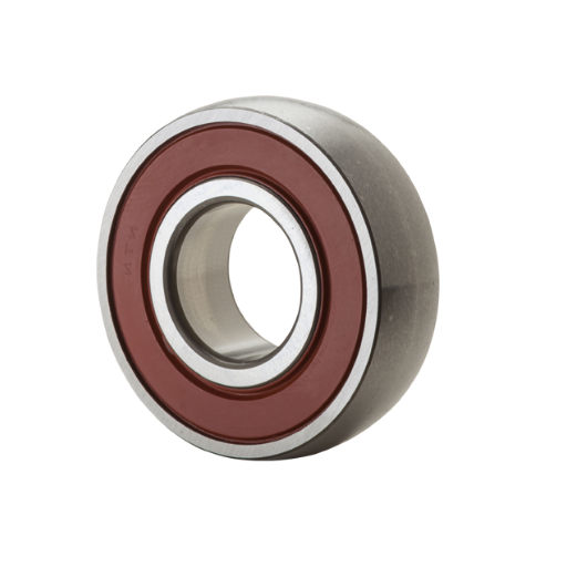
Bearing fits in the automotive industry are mainly about guaranteeing durability and efficiency for such crucial components as engines, transmissions, and wheels. The objective is a perfect fit to reduce vibration and friction in moving parts working under varied load and speed conditions; whereas an interference fit may be used for ensuring the relative stability of parts during high-speed rotations, like crankshaft and camshaft assemblies, a clearance fit becomes necessary where free controlled movement or thermal expansion is considered, such as in wheel bearings.
Indeed, material selection contributes a great deal toward the quality of bearing fits. To meet operational temperatures and load conditions in automotive applications, advanced alloys or composite materials are mostly chosen. Then there are manufacturing processes, such as precision grinding and laser machining, which enable assemblies to maintain much tighter tolerances with less deviation.
Bearing fits also require monitoring throughout the vehicle lifecycle. This monitoring is done via prediction and enhancement maintenance solutions, along with machine learning and sensor-tech enhancements, so as to detect misalignment or wear early, thereby avoiding possible mechanical failures. With the introduction of such advanced methods integrating traditional fitting standards, the automotive world appears to be one step ahead in ensuring respect for reliability and performance in its designs.
Aerospace Applications: Safety and Reliability
In aerospace engineering, utmost importance is given to safety and reliability, where precision and stringent standards must be met. The industry, through advanced technologies and strict protocols, ensures that aircraft, spacecraft, and their support systems can withstand the most demanding conditions. The following five methods and technologies form the basis of enhancing safety and reliability in aerospace applications:
- Redundant Systems Architecture: Aerospace systems create redundancy in crucial parts like avionics, hydraulics, and propulsion systems. By duplicating essential systems, they ensure functionality in the event of failure, greatly minimizing the prospects of a catastrophic accident.
- Predictive Maintenance via Data Analytics: These advanced predictive maintenance techniques use machine learning algorithms combined with the analysis of real-time sensor data to predict the wear and possible failure of components. This approach is an alternative to traditional methods where maintenance is carried out after an unexpected failure causes an incident; instead, these methods help predict and minimize incidents of unscheduled downtime.
- Material Science Innovations: In the realm of aerospace, innovative lightweight composite materials such as carbon fiber reinforced polymers impart structural integrity and durability to the aerospace vehicles while reducing weight to improve fuel efficiency and performance.
- Testing and Certification Process: Aerospace hardware undergoes thorough testing and certifications, comprising vibration, thermal, fatigue, and wind tunnel testing of the various components involved in the apparatus to prove their ability to withstand extreme conditions.
- Enhanced Pilot Assistance Systems: The modern-day cockpit is endowed with enhanced pilot assistance systems, such as fly-by-wire control and automated decision aid systems, which ease pilot workload, besides helping them make better decisions in critical phases such as takeoff or landing.
Together, these measures provide a thorough set of safeguards so that the aerospace systems deliver on the highest safety and reliability benchmarks, catering not only to technological needs but also to passenger trust.
Tips for Ensuring Optimal Performance
Best Practices in Precision Machining
For the manufacturing process, precision machining stands on a delicate balance of advanced technology, perfect planning, and execution. For any machining job, a set of best practices needs to be strictly adhered to to attain the best possible result; this ensures accuracy, efficiency, and maintenance of the machines as well as the finished components.
- Buy High-Quality Equipment and Maintain it Properly: Precisely machining depends on how well the machine is performing. CNC machines with high quality and state-of-the-art features like adaptive controls, real-time monitoring systems, etc., will yield greater accuracy. Along with acquiring a good machine, it is equally essential to keep in place rigorous maintenance schedules, which include timely replacement of parts, monitoring of tool conditions, and ensuring adequate lubrication at all times; this will reduce downtime and increase the lifespan of the machines.
- Selection and Preparation of Materials: Material selection has a paramount influence on the results of precision machining. The hardness, thermal conductivity, and elasticity of a material influence its behavior in machining, as well as tool wear. Materials should be evaluated for their compatibility in meeting the required tolerances and finishes. Pre-conditioning of materials by stress relieving or annealing will reduce the chances of it deforming during machining, hence increasing the accuracy and dimensional stability of the end product.
- Tooling Optimization and Calibration: Precision machining requires not only high-grade tooling but their optimal arrangement and maintenance. Cutting tools should be coated in a way that suits the material being processed; for example, titanium nitride should be used for steel and diamond coating for composite workpieces. Tools and instrument setups should be calibrated routinely to ensure they are within tight tolerances. Documenting tool offsets, wear conditions, and operational parameters clearly can drastically improve repeatability and lessen the incidence of operator errors during succeeding operations.
- Advanced Software Integration: The integration of advanced software solutions into machining processes proves indispensable in the quest for modern-day precision. With CAM software being one, just alongside powerful simulation tools that allow machinists to verify workflows, foresee issues, and curtail wastes, a data-driven approach such as predictive analytics could also pinpoint system performance, therefore enabling proactive tuning and long-term process improvements.
By instilling these best practices within their operations, manufacturers are capable of keeping up with their products’ quality while gaining leverage in reducing inefficiencies, as well as gaining an edge in the impending environment of precision machining. These highly advanced technologies, combined with very systematic practices, ensure that all operations are carried out under stringent industry standards, serving both client needs and safety requirements.
Importance of Lubrication for Bearing Fit
Bearing systems consist of mechanical elements that generally contain a mating fit. The lubrication assures proper bearing fit and performance in its mechanical system. Lubrication separates frictional forces between the two bearing surfaces; without lubrication, friction leads to wear and tremendous heating of the bearing surfaces, thus leading to eventual bearing failure. The lubricant also forms a film that acts as a corrosive barrier, preventing corrosion and contamination by dust and other undesirable contaminants, moisture, and abrasive particles.
Studies show that improper lubrication accounts for anywhere between 50 percent and 80 percent of bearing failures in industrial applications. Choosing the kind of lubricant, oil, or grease, and its viscosity quality, depending on the load, speed, and operating temperature, is a determining factor for an ideal bearing. For instance, high-viscosity lubricants would be required for heavy loads, whereas low-viscosity lubricants suit high-speed operations.
Modern generations of lubrication technologies, such as synthetic lubricants or solid lubricant coatings, provide higher thermal stability and lifespan extension. Further, the automated lubrication systems have been widely employed for the delivery of lubricants at predetermined time intervals, ensuring unvarying performance and reduced maintenance. By converging subsequent emphasis into lubricating methods, equipment downtime can be lessened, while machine efficiency gets optimally maintained, together with bearing life extension.
Regular Maintenance for Longevity
Regular maintenance constitutes a fundamental need of medicine for the optimal performance and extended service life of machinery and mechanical systems. With an organized maintenance plan, an establishment shall anticipate a major problem and fix it before it turns into a catastrophic failure. Inspection of critical components such as seals, bearings, and lubrication systems must be carried out since these components are most susceptible to wear and degeneration. The use of diagnostic tools such as vibration analyses, thermal imaging, and ultrasonic testing helps maintenance teams in identifying preliminary signs of mechanical stress or misalignments.
In balance with other fields, predictive maintenance has profited from recent technological advancements to initiate its rise through condition monitoring conducted in real-time. These systems use sensors and IoT technology to collect ever-changing information about temperature, pressure, and vibration, thus presenting decision-makers with detailed data.
While regular inspection is very good for maintenance, a condition-based monitoring system becomes a good complement to these inspections. The maintenance records should also be taken care of while maintaining a check on manufacturers’ specifications so that all performance standards are satisfied. This multidimensional approach is a necessary investment for safeguarding the machinery and decreasing unnecessary downtime and operational costs, which indirectly ensures sustained efficiency and reliability in an industrial setting.
Frequently Asked Questions (FAQ)
Q: What is bearing fit?
A: Bearing fit indicates how the bearing is related to its shaft or housing in which it is installed. This also means that, depending on the tolerance specification of the bearing fit, the bearing can be clamped tightly or loosely in position, thereby affecting bearing operation and life. Ensuring proper bearing fit will minimize problems like creep and wear.
Q: What is the difference between press fit and sliding fit?
A: A press fit is a kind of bearing fit where the inner ring of the bearing is tightly fitted onto the shaft, and assembly is often by force. A sliding fit allows the bearing and shaft to be readily assembled and disassembled. The choice depends on the application for which it is being selected.
Q: How to calculate the shaft diameter required for bearing fit?
A: To calculate the shaft diameter required for bearing fit, the information should be about the inside diameter of the bearing and the fit required. For press fitting, the diameter of the shaft should be slightly greater than the diameter of the inner ring, whereas for the sliding fit, the diameter should be closer to the inside diameter, allowing some movement.
Q: What are the causes of bearing fit problems?
A: Incorrect installation, nonexistent housing bore diameters, varying distances, or thermal expansion may cause bearing fit problems. Also, the use of the wrong fit, for example, a loose fit, can cause the premature failure of the bearings in a high-load application.
Q: What is important about the outer ring and the fitting thereof?
A: Typically, the bearing outer ring is press-fitted to the housing bore. A good fit prevents the outer ring from moving and thus allows its inner counterpart and shaft to rotate freely. In the absence of such a fit, the outer ring may move and cause heavy wear and eventual failure because of misalignment or vibration.
Q: What is the importance of bearing outside diameter?
A: The bearing outside diameter must correspond to the housing bore to cling firmly. If it is smaller, the bearing will get loose and vibrations will start, and failure may be a possibility. If the size is bigger, the bearing will not fit inside, so the problem will be installation.
Q: Does bearing fit affect a ball and roller bearing?
A: A bearing fit directly influences the performance of both ball and roller bearings. A suitable fit provides optimal loading conditions and ensures minimum wear. A loose fit could lead to excessive movement and creep, whereas a tight fit will increase friction and temperature, thus affecting the bearing life.
Q: What should be mentioned while selecting a fitting for a bearing for my application?
A: While selecting a fit for bearing type, of loading, operating conditions, and materials must be considered first. Before deciding, one must study the shaft diameter, housing bore, and type of bearing (ball or roller) on which he is working so that the fit eventually selected fulfills the requirements of his application.
UCTH213-40J-300 with Setscrew(inch)
CNSORDERNO: Normal-duty(2)
TOGN: UCTH213-40J-300
SDI: B-R1/8
SD: 2 1/2
UCTH212-39J-300 with Setscrew(inch)
CNSORDERNO: Normal-duty(2)
TOGN: UCTH212-39J-300
SDI: B-R1/8
SD: 2 7/16
UCTH212-38J-300 with Setscrew(inch)
CNSORDERNO: Normal-duty(2)
TOGN: UCTH212-38J-300
SDI: B-R1/8
SD: 2 3/8
UCTH212-36J-300 with Setscrew(inch)
CNSORDERNO: Normal-duty(2)
TOGN: UCTH212-36J-300
SDI: B-R1/8
SD: 2 1/4
UCTH211-35J-300 with Setscrew(inch)
CNSORDERNO: Normal-duty(2)
TOGN: UCTH211-35J-300
SDI: B-R1/8
SD: 2 3/16
UCTH211-34J-300 with Setscrew(inch)
CNSORDERNO: Normal-duty(2)
TOGN: UCTH211-34J-300
SDI: B-R1/8
SD: 2 1/8


